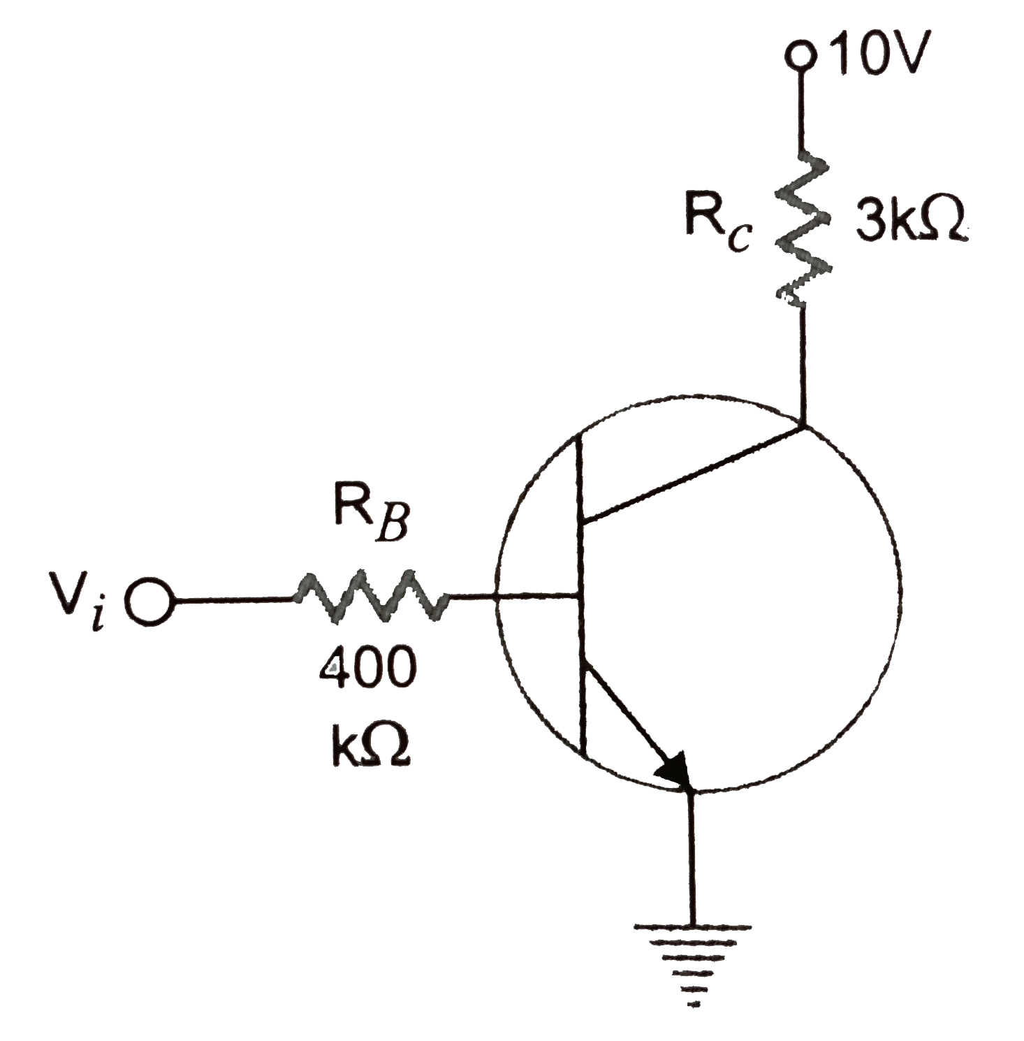
In the circuit shown in figure when the input voltage of the base resistance is 10 V . Find the values of Ib,Icandβ .
Video Solution
Text Solution
The correct Answer is:A, B, C
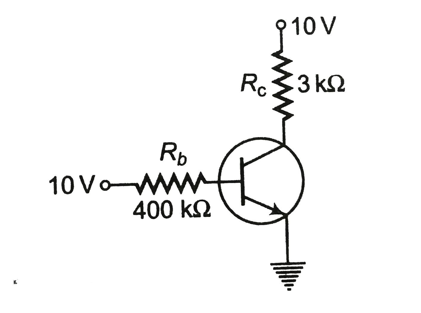
Given circuit is equivalent to
(##DCPV05C35E01025_S01.png width=80%><br>Inbaseemierl∞p,<br> V_B = I_B R_B <br> rArr I_B = V_B / R_B = 10 / (400 xx 10^(3))<br> = 25 xx 10^(-6) A <br> = 25 mu A <br>Inemier−col≤c→rl∞p,<br> V_C = I_C R_C <br> rArr I_C = 10 / (3 xx 10^(3)) <br> and βDC=ICIB=3.33mA25μA
=133
|
Topper's Solved these Questions
- SEMICONDUCTORSBOOK - DC PANDEYCHAPTER - SEMICONDUCTORSEXERCISE - More Than One Correct
6 Videos
- REFRACTION OF LIGHTBOOK - DC PANDEYCHAPTER - REFRACTION OF LIGHTEXERCISE - Level 2 Subjective
21 Videos
- SOLVED PAPER 2017BOOK - DC PANDEYCHAPTER - SOLVED PAPER 2017EXERCISE - Solved papers 2017(JIPMER)
32 Videos
Similar Questions
Knowledge Check
In the circuit shown in figure, when the input voltage of the base resistance is 10 V, Vbe is zero and Vce is also zero. Then
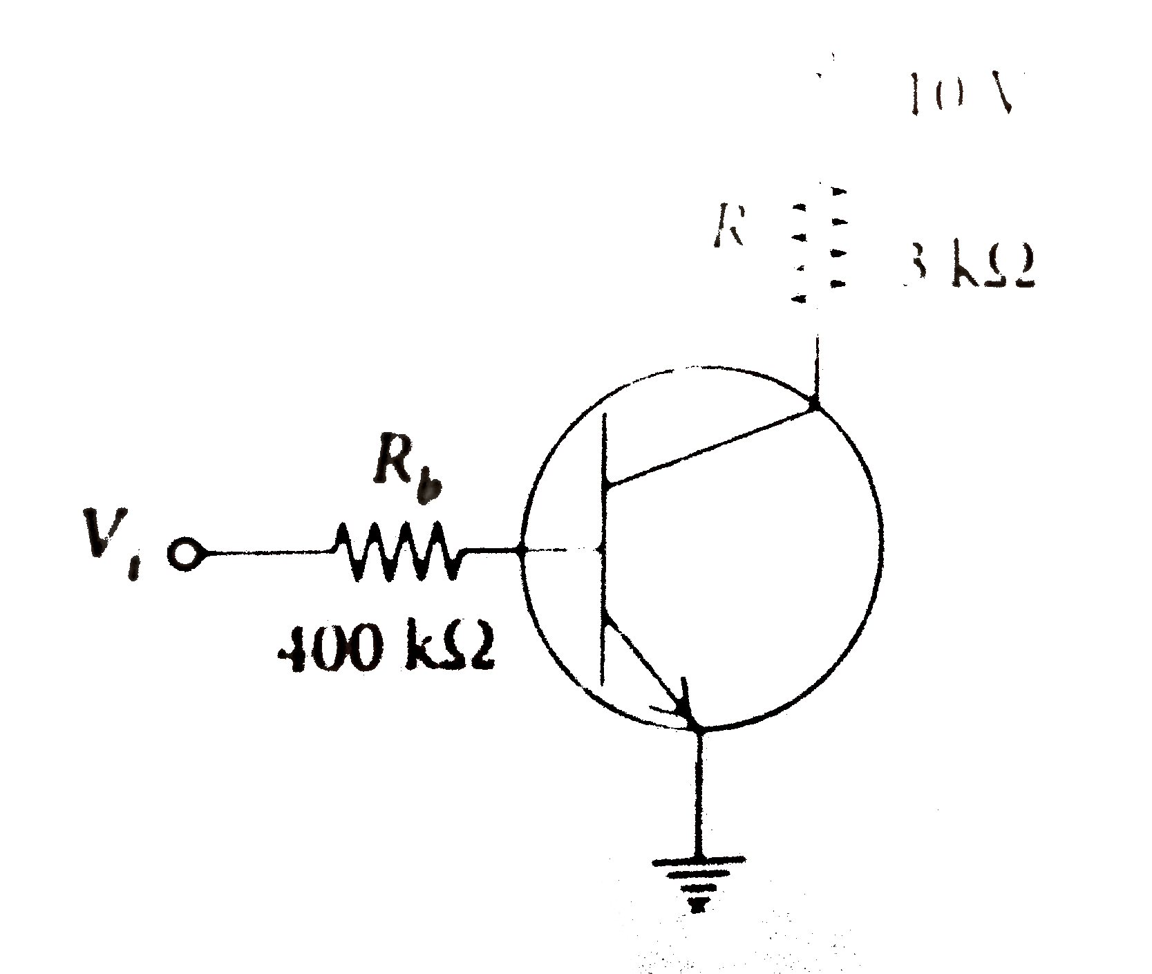 Aβ=110BIb=25μACIc=3.33mADboth (A) and (C )
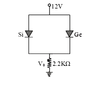
In the circuit shown in figure, Voltage V0 is
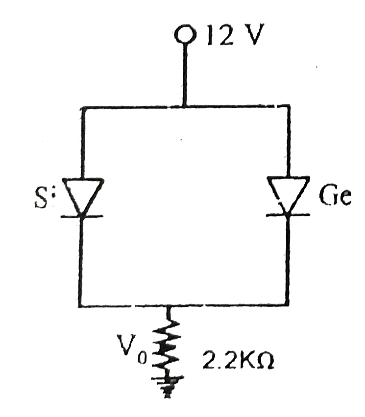 A11.7 voltB11.3 voltC0DNone
In the circuit shown in the figure
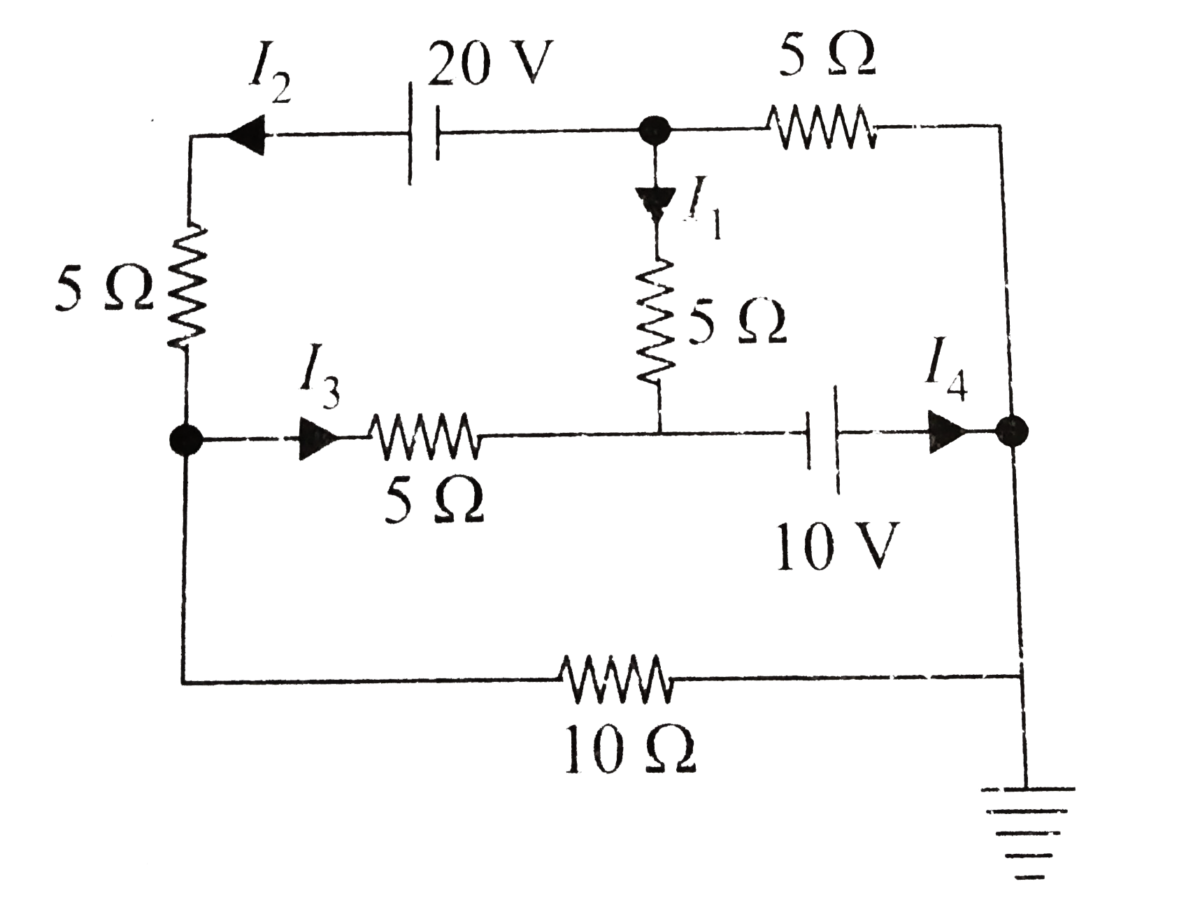 .
.
The value of current I4 isA2ABzeroC2.5 ADnone of these
In the circuit shown in Fig.
if we assume that when the input voltage at the base resistance is 5V,VBE is zero and VCE is also zero. What is I,I and beta?
When the input is zero, then I is zero. What would be the output wave form if the input wave form is as shown in Fig.
View SolutionIn the circuit shown in the figure
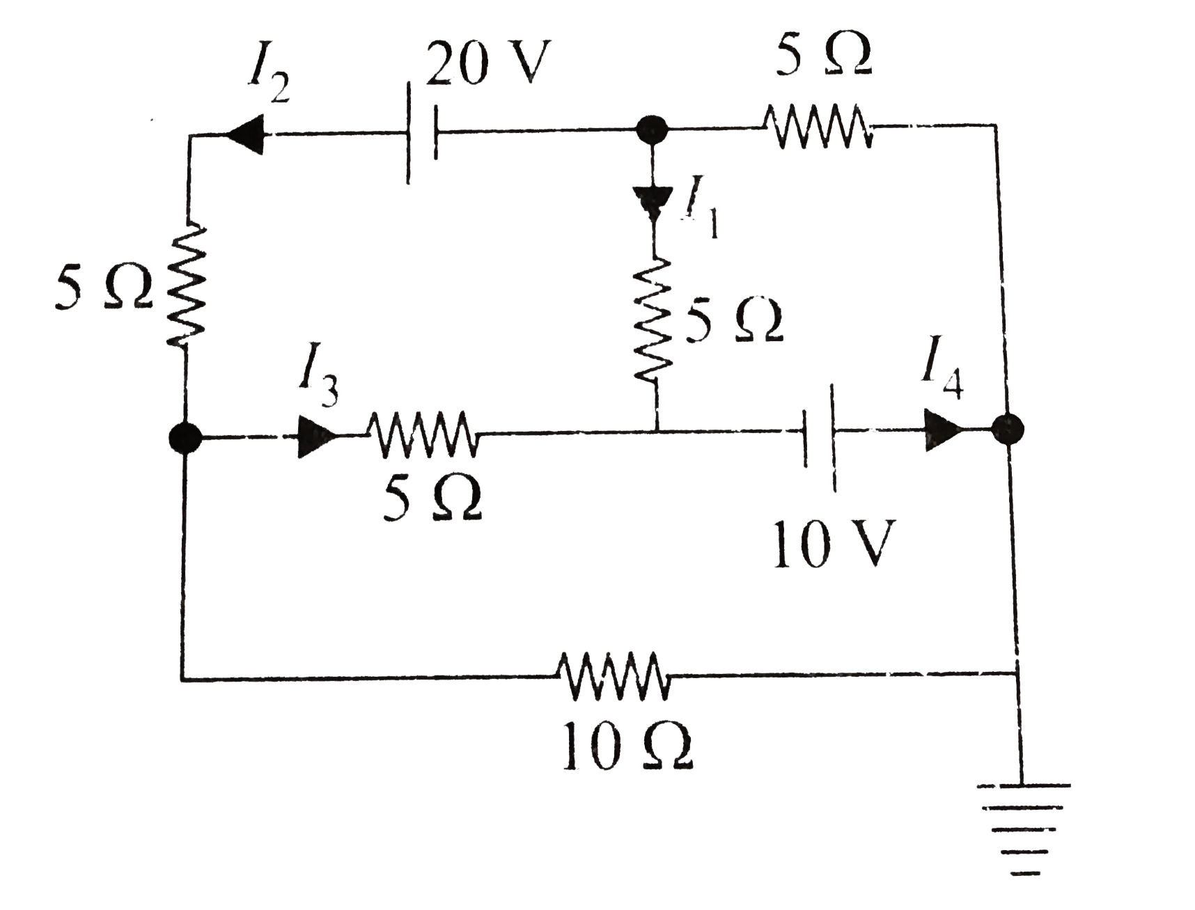 .
.
The value of current I1 is
View SolutionIn the circuit shown in the figure, the input voltage Vi is 20V,VBE=0 and VCE=0. The values of IB,IC and β are given by:
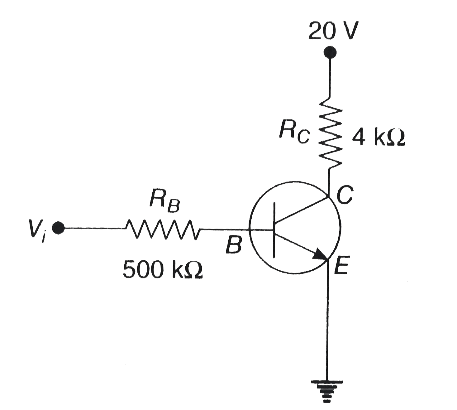
View SolutionIn the circuit shown in the figure, the input voltage Vi is 20V, VBE=0 and VCE=0. The values of IB, IC and β are given by
View SolutionIn the circuit shown in the figure, the input voltage Vi is 20V,VBE=0 and VCE=0. The values of IB,IC and β are given by:

View Solution

