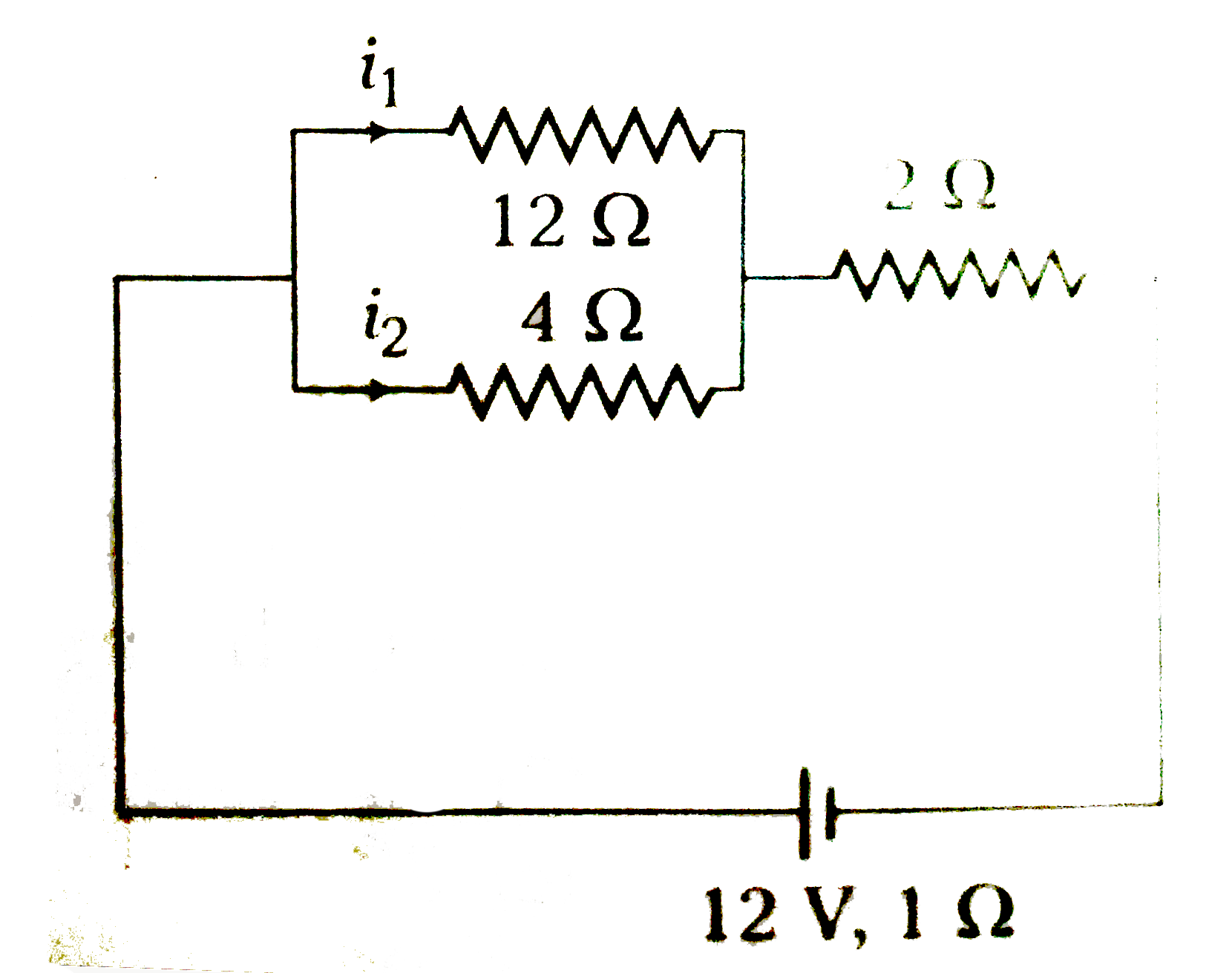
In the circuit shown, the currents i1 and i2 are
A
i1=1.5A,i2=0.5A
B
i1=0.5A,i2=1.5A
C
i1=1A,i2=3A
D
i13A,i2=1A
Video Solution
Text Solution
The correct Answer is:B
Resistance R=12×412+4+2=4816+2=5Ω
Electric current i=ER+r=126=2A
∴ i1+i2=2A …..(i)
i∝1R⇒l1R1=l2R2
l1=R2R1l2⇒l1=13l2 ltbr This value in the eq. (i) and we get
∴ i2=1.5A,i1=0.5A
|
Updated on:21/07/2023
Topper's Solved these Questions
- BOOK - MHTCET PREVIOUS YEAR PAPERS AND PRACTICE PAPERSCHAPTER - CURRENT ELECTRICITYEXERCISE - EXERCISE 226videos
CURRENT ELECTRICITY
- BOOK - MHTCET PREVIOUS YEAR PAPERS AND PRACTICE PAPERSCHAPTER - CURRENT ELECTRICITYEXERCISE - MHT CET CORNER32videos
CURRENT ELECTRICITY
- BOOK - MHTCET PREVIOUS YEAR PAPERS AND PRACTICE PAPERSCHAPTER - CURRENT ELECTRICITYEXERCISE - MHT CET CORNER32videos
CURRENT ELECTRICITY
- BOOK - MHTCET PREVIOUS YEAR PAPERS AND PRACTICE PAPERSCHAPTER - COMMUNICATION SYSTEMEXERCISE - MHC CET Corner6videos
COMMUNICATION SYSTEM
- BOOK - MHTCET PREVIOUS YEAR PAPERS AND PRACTICE PAPERSCHAPTER - ELASTICITY EXERCISE - MHT CET CORNER16videos
ELASTICITY
Similar Questions
Knowledge Check
- Question 1 - Select One
In the circuit shown, the value of currents I1,I2andI3 are
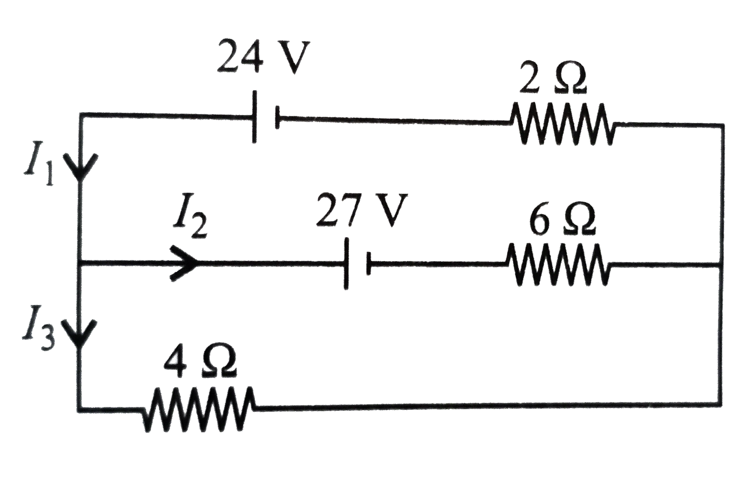 A3A,−3A2A,92AB92A,−32AC5A,4A,−3AD7A,54A,92A
 - Question 2 - Select One
In the given circuit the current I1 is
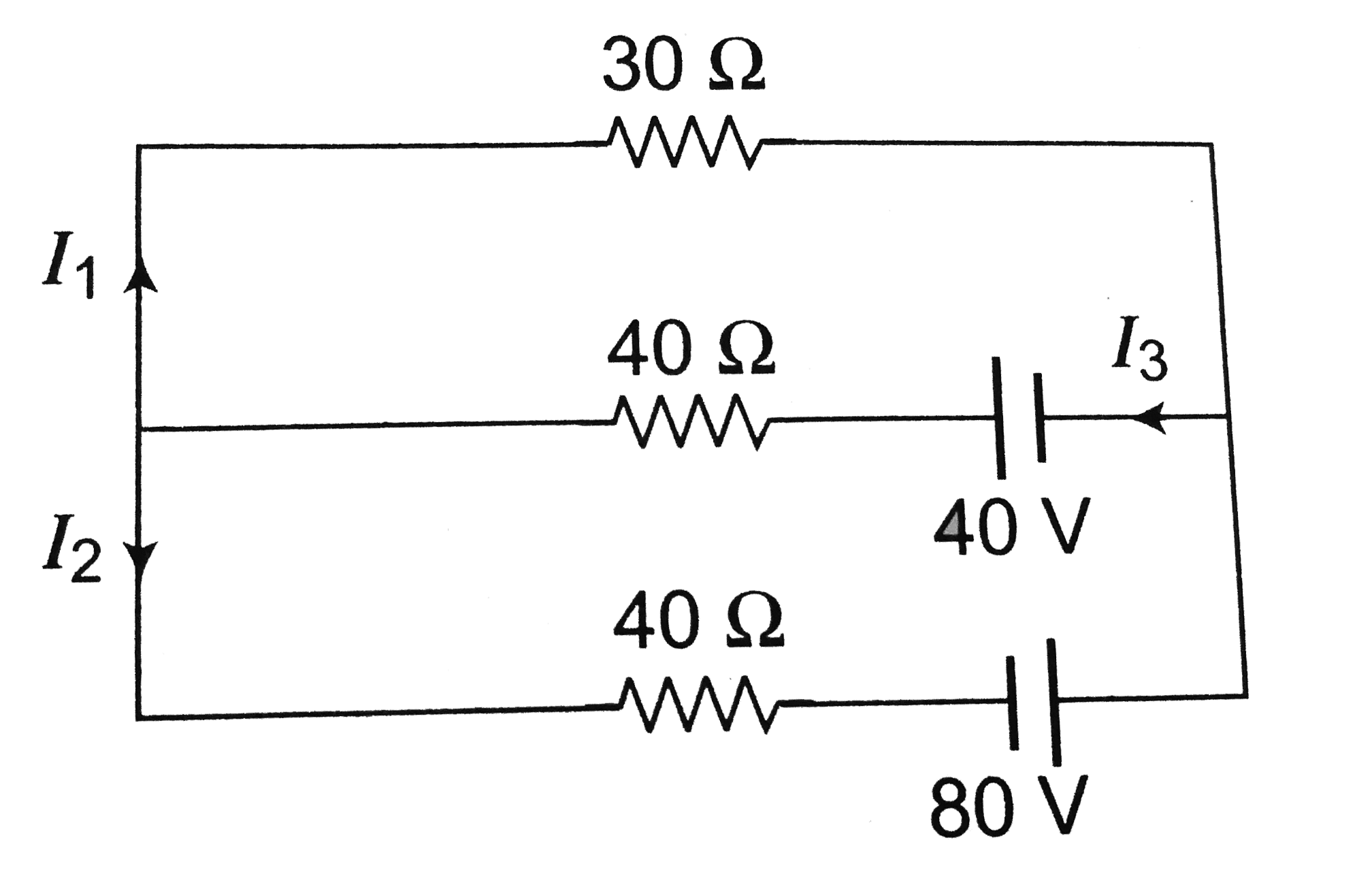 A0.4AB−0.4AC0.8AD−0.8A
 - Question 3 - Select One
In the circuit shown if fig, the rims currents (I1),(I2) and(I3) are altered by varying the freqency f of the oscillator. The output voltage of the oscillatro remains sinusoidal and has a fixed amplitude.
When curves in figure correctly indicate the variation with frequency of the currents (I1),(I2),and(I3).
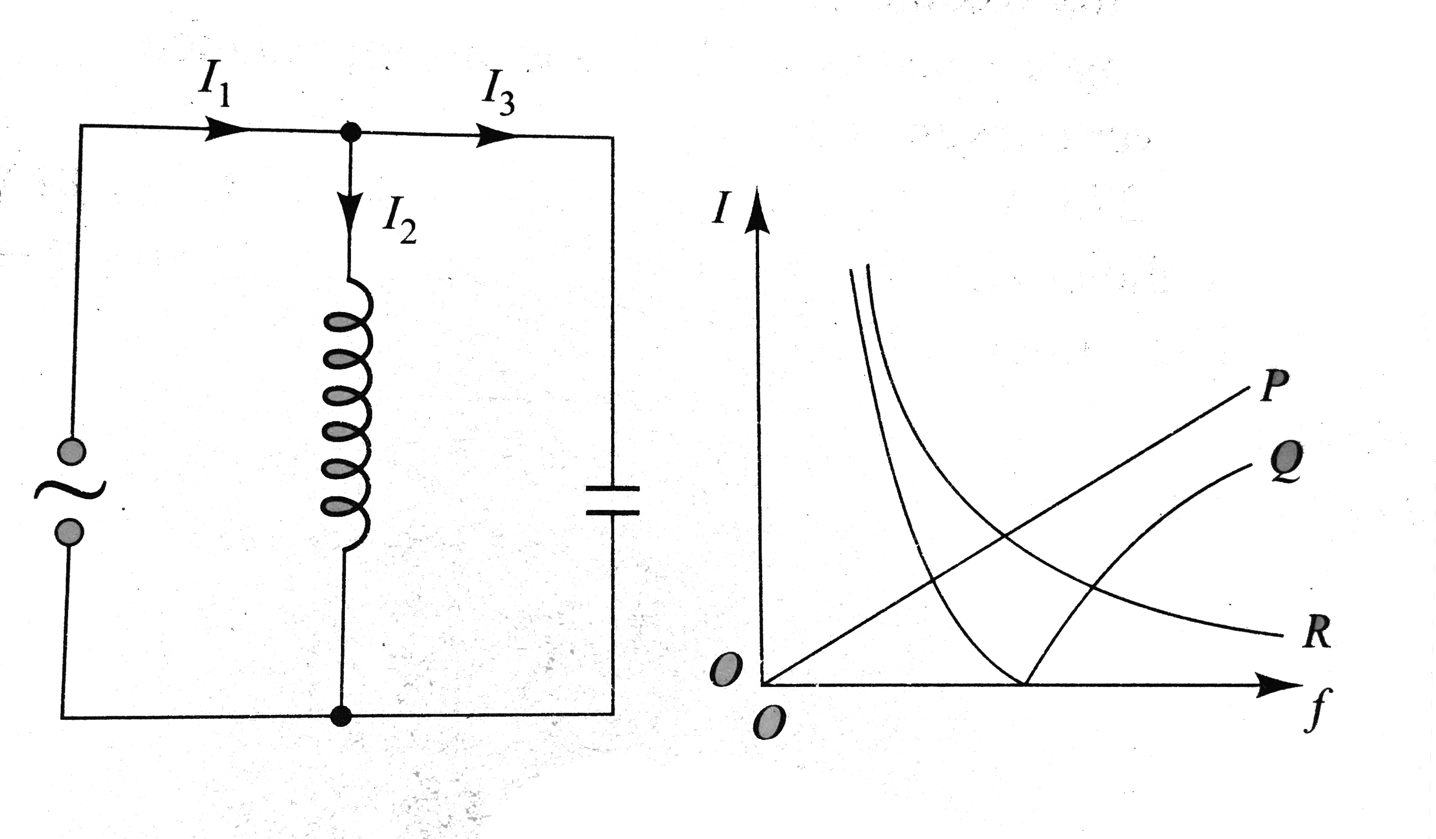 A(A)(I1)=Q, (I2)=Q, (I3)=QB(B)(I1)=R, (I2)=Q, (I3)=QC(C) (I1)=Q, (I2)=P, (I3)=RD(D)(I1)=Q, (I2)=R, (I3)=P
In the circuit shown, the current I will be zero when R is
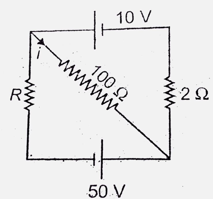 View Solution
In the circuit shown in figure,the base current IB is 10μA and the collector current is 5.2 mA . The voltage (VBE) across the base and emitter is
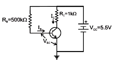 View Solution
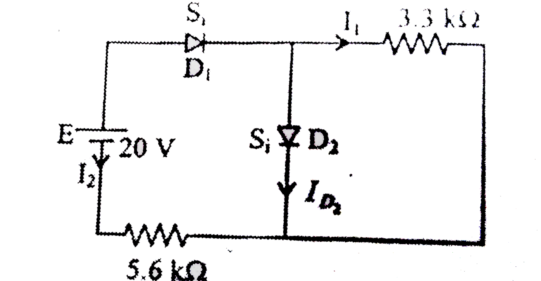
In the circuit shown in figure I1,I2 and ID2 are respectively-
 View Solution
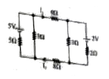
In the circuit shown, the ratio I1I2 is equal to
 View Solution
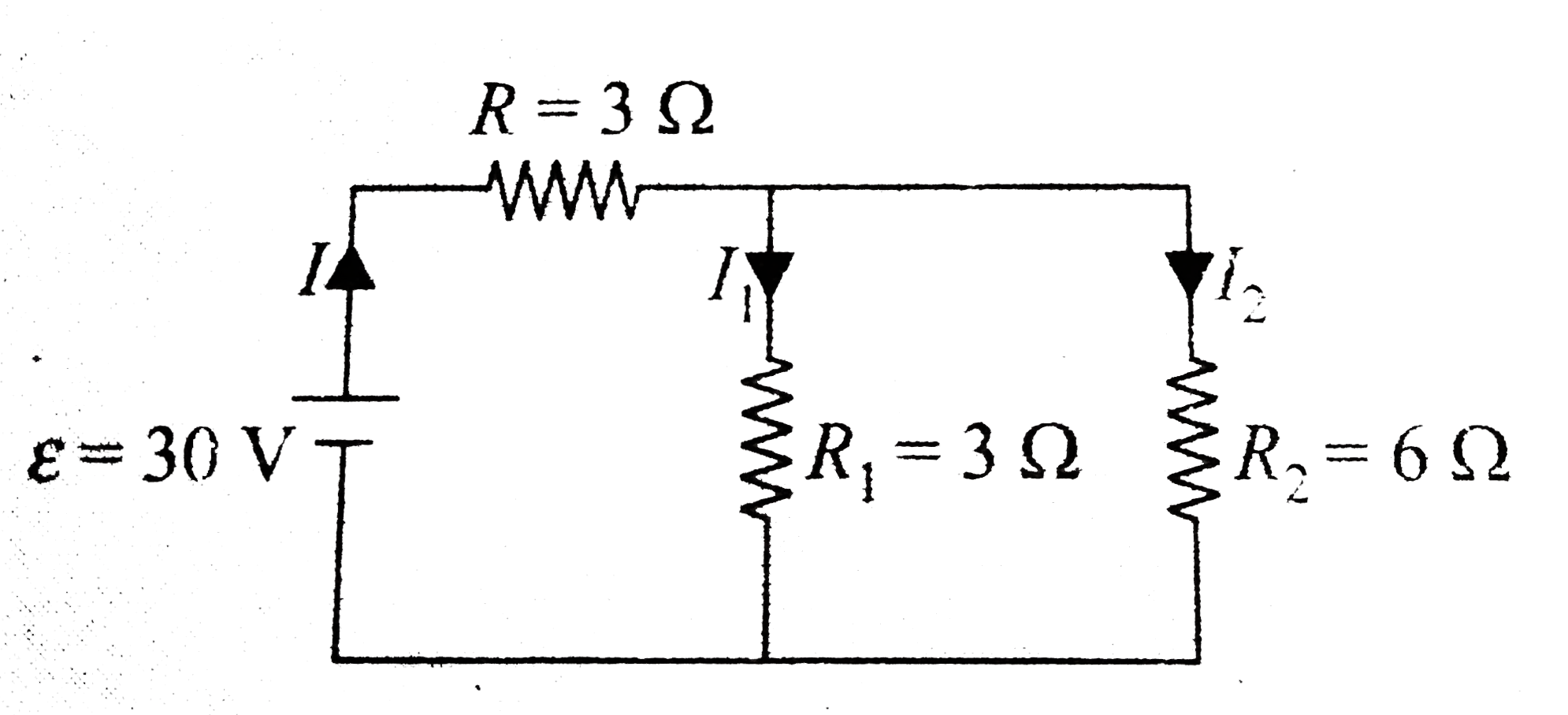
In the circuit given, find the currents I, I1 and I2 in the circuit.
 View Solution


