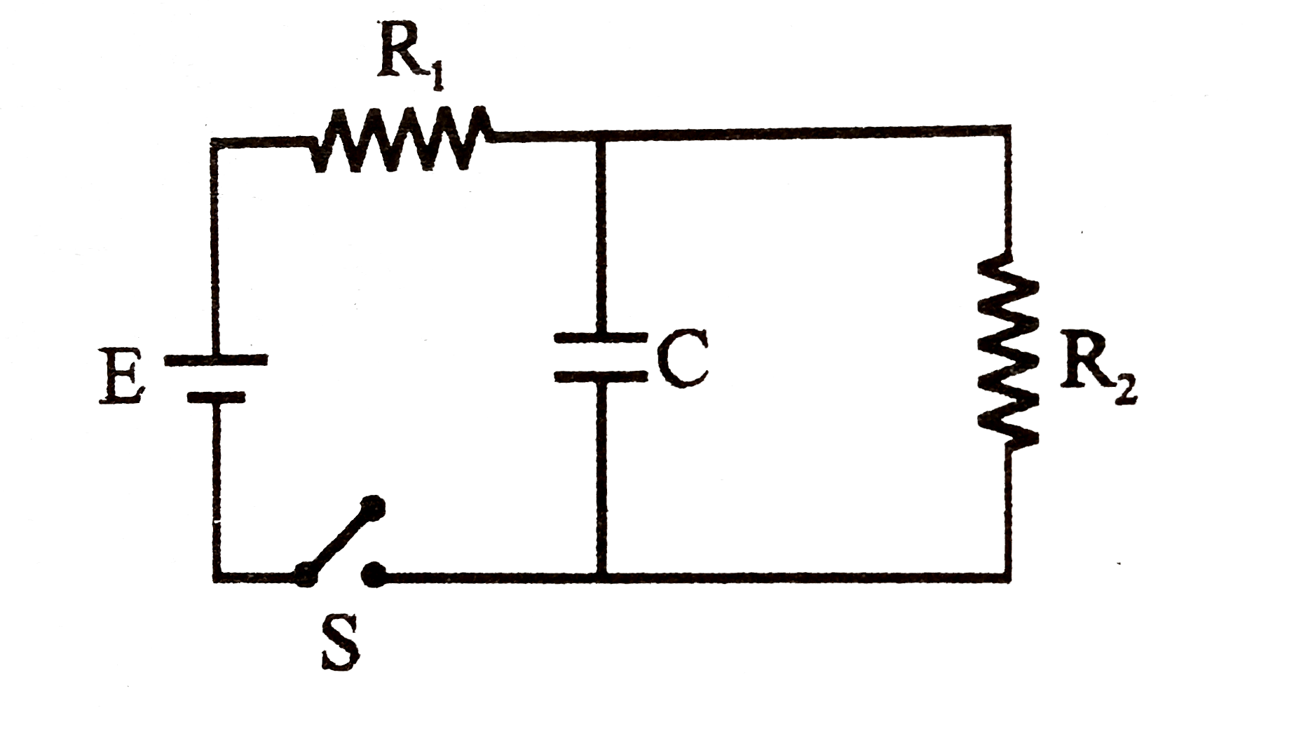
For the arrangement shown in the switch is closed at t =0. The time after which the current becomes 2.5μAS is given by (take in 2 =0.69)

10 S
5 S
7 S
0.693 S
The correct Answer is:C
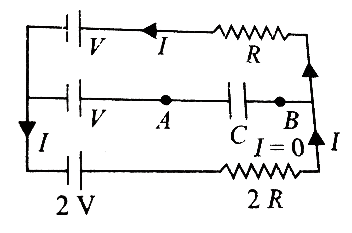
In the steady-state conducting,
no current will flow through the
capacitor C.
Current in the outer circuit
I=2V−V2R+R=V3R
Potential difference between A and B is
VA−V+V+IR=VBorVB−VA=IR=(V3R)R=V3
Topper's Solved these Questions
- ELECTRIC CURRENT AND CIRCUITBOOK - CENGAGE PHYSICSCHAPTER - ELECTRIC CURRENT AND CIRCUITEXERCISE - Multiple Correct
16 Videos
- ELECTRIC CURRENT AND CIRCUITBOOK - CENGAGE PHYSICSCHAPTER - ELECTRIC CURRENT AND CIRCUITEXERCISE - Comprehension
35 Videos
- ELECTRIC CURRENT AND CIRCUITBOOK - CENGAGE PHYSICSCHAPTER - ELECTRIC CURRENT AND CIRCUITEXERCISE - Subjective
29 Videos
- ELECTRIC CURRENT & CIRCUITSBOOK - CENGAGE PHYSICSCHAPTER - ELECTRIC CURRENT & CIRCUITSEXERCISE - Kirchhoff s law and simple circuits
15 Videos
- ELECTRIC FLUX AND GAUSS LAWBOOK - CENGAGE PHYSICSCHAPTER - ELECTRIC FLUX AND GAUSS LAWEXERCISE - MCQ s
38 Videos
Similar Questions
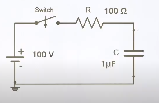
The switch is closed at t=0. Find time after which voltage across capacitor becomes 50 V. (take ln 2 = 0.6)
View SolutionFor the arrangement shown in the figure, the switch is closed at t=0. C2 is initially uncharged while C1 has a charge of 2μC
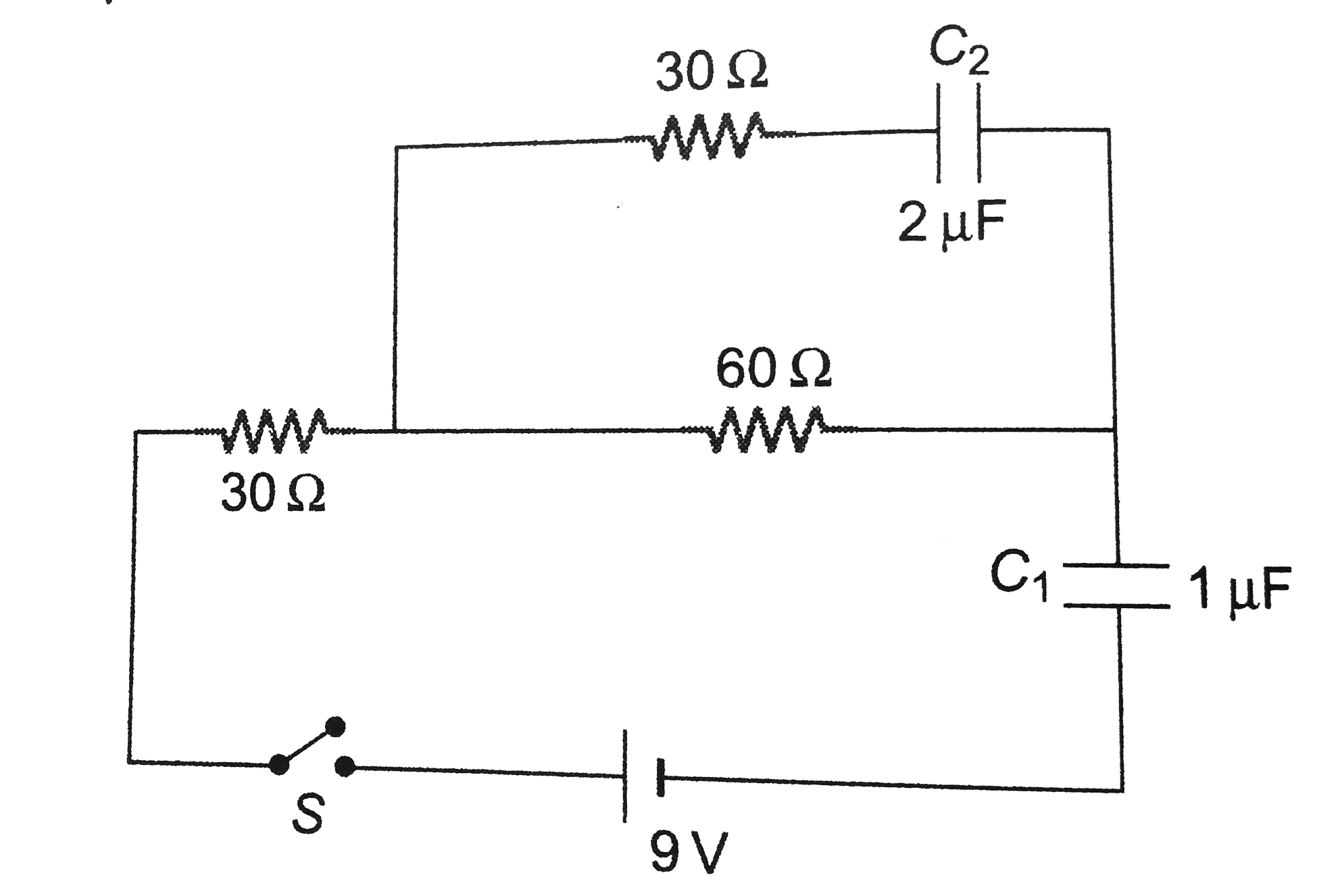
(a) Find the current comingn out of the battery just after the switch is closed.
(b) Find the charge on the capacitors in the steady state condition.
View Solution
Knowledge Check
In the circuit as shown in figure the switch is closed at t=0.
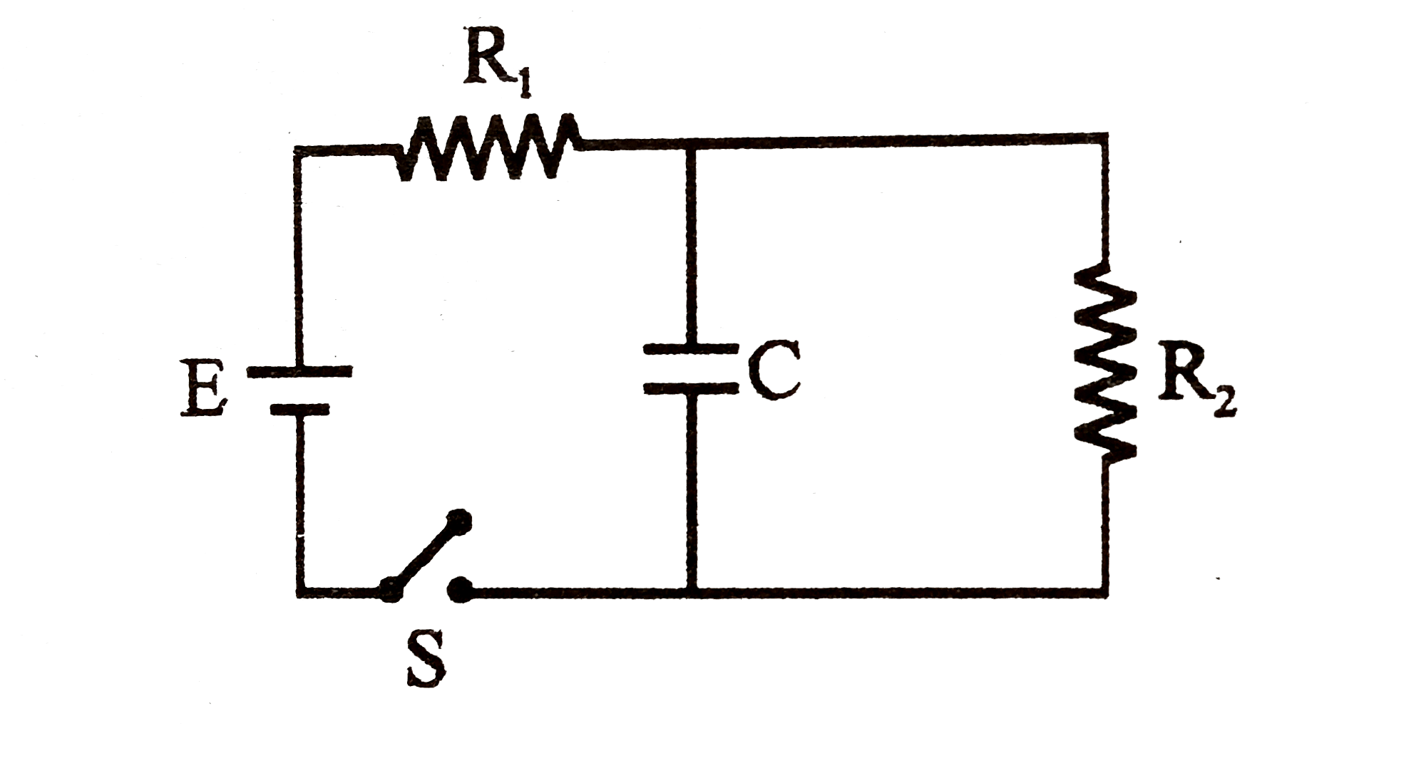
A long time after closing the switchAvoltage drop across the capacitor is EBcurent through the battery is E/R1+R2Cenegru stores in the capacitor is
12C(R2ER1+R2)2Dcurrent through the capacitor becomes zero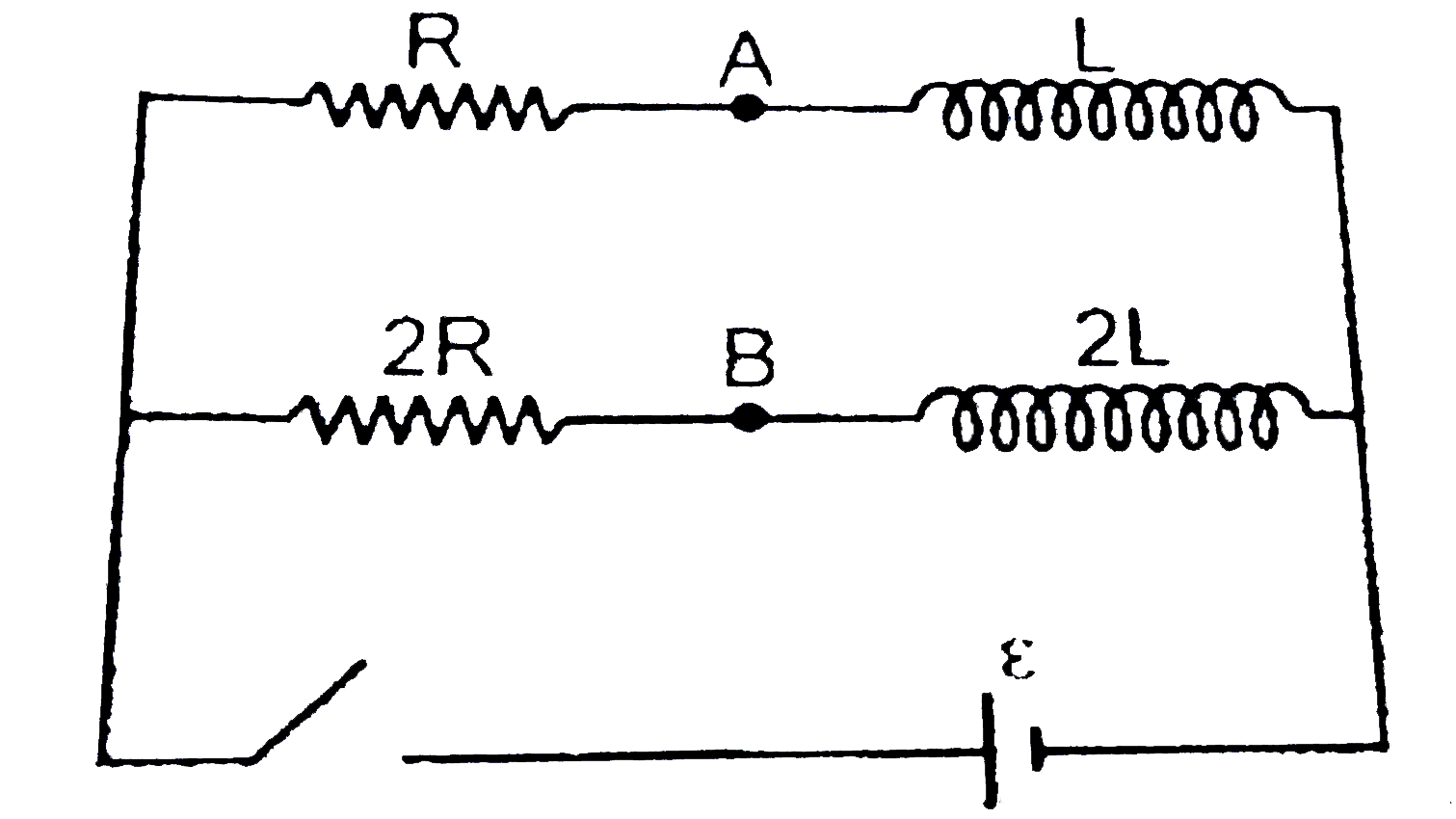
In given LR circuit the switch S is closed at time t=0 thenAThe ratio of induced emfs in the inductors of inductance L and 2L will be constantBThe ratio of induced emfs in the inductor of inductance L and 2L will be time varyingCthe potential difference VA−VB increases with timeDThe potential difference VA−VB will be constantIn the circuit shown in the figure, switch S is closed at time t=0. Select the correct statements.
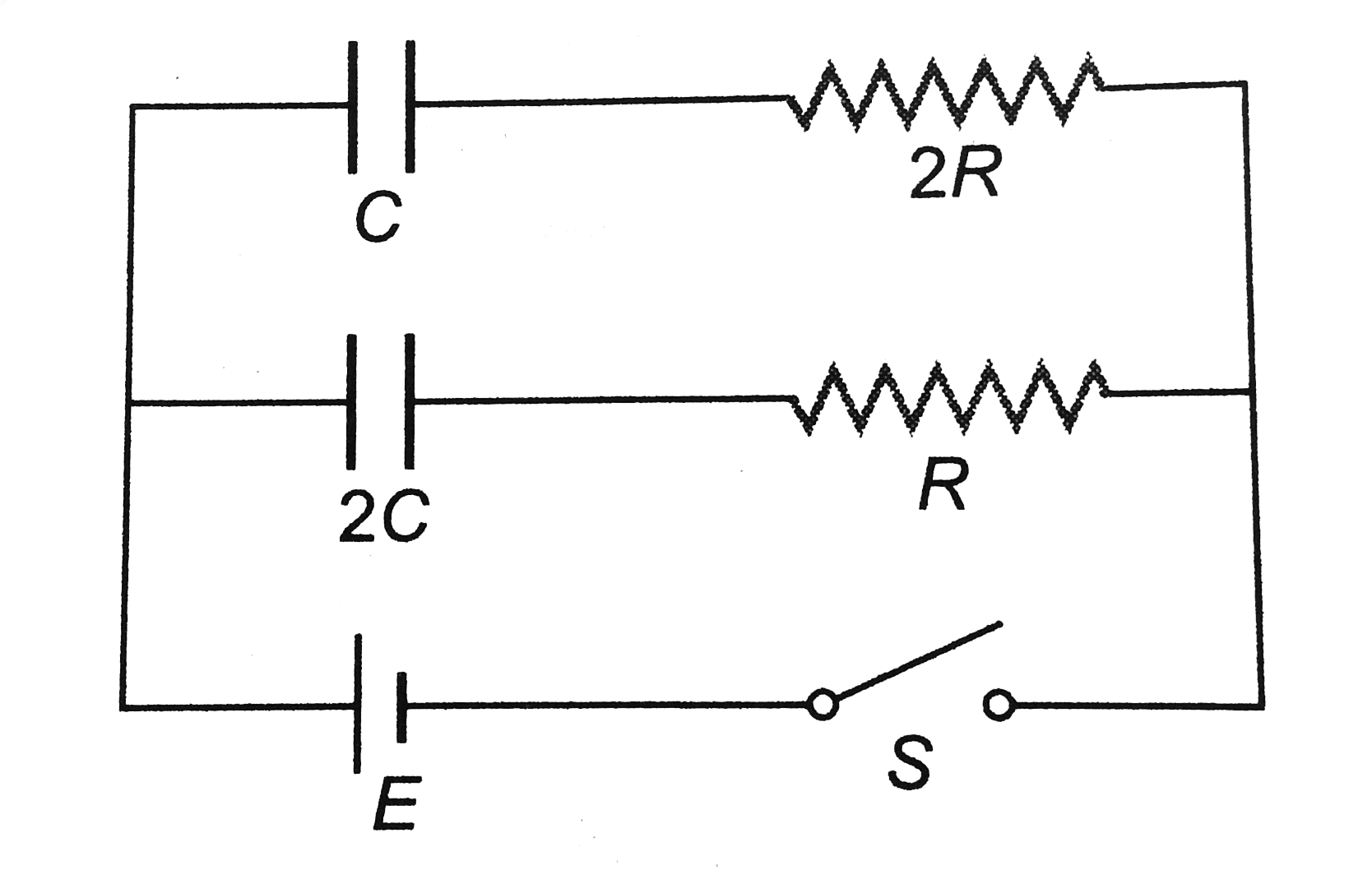 ARate of increase of charge is same in both the capacitorsBRatio of charge stored in capacitors C and 2C at any time t would be 1:2CTime constants of both the capacitors are equalDSteady state chares on capacitors C and 2C are in the ratio of 1:2
Switch is closed at t=0 then the current in the circuit at t=L2R is
_PHY_E06_157_Q01.png)
View SolutionIn the circuit shown in figure switch S is closed at time t=0
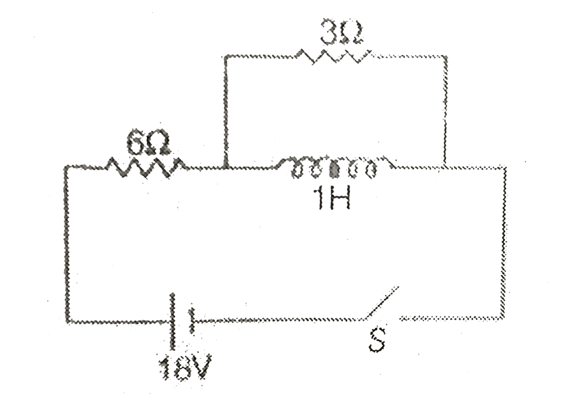
Current I from the battery at time t is given by
View SolutionIn adjacent circuit, switch S is closed at t = 0. The time at which current in the circuit becomes half of the steady current is
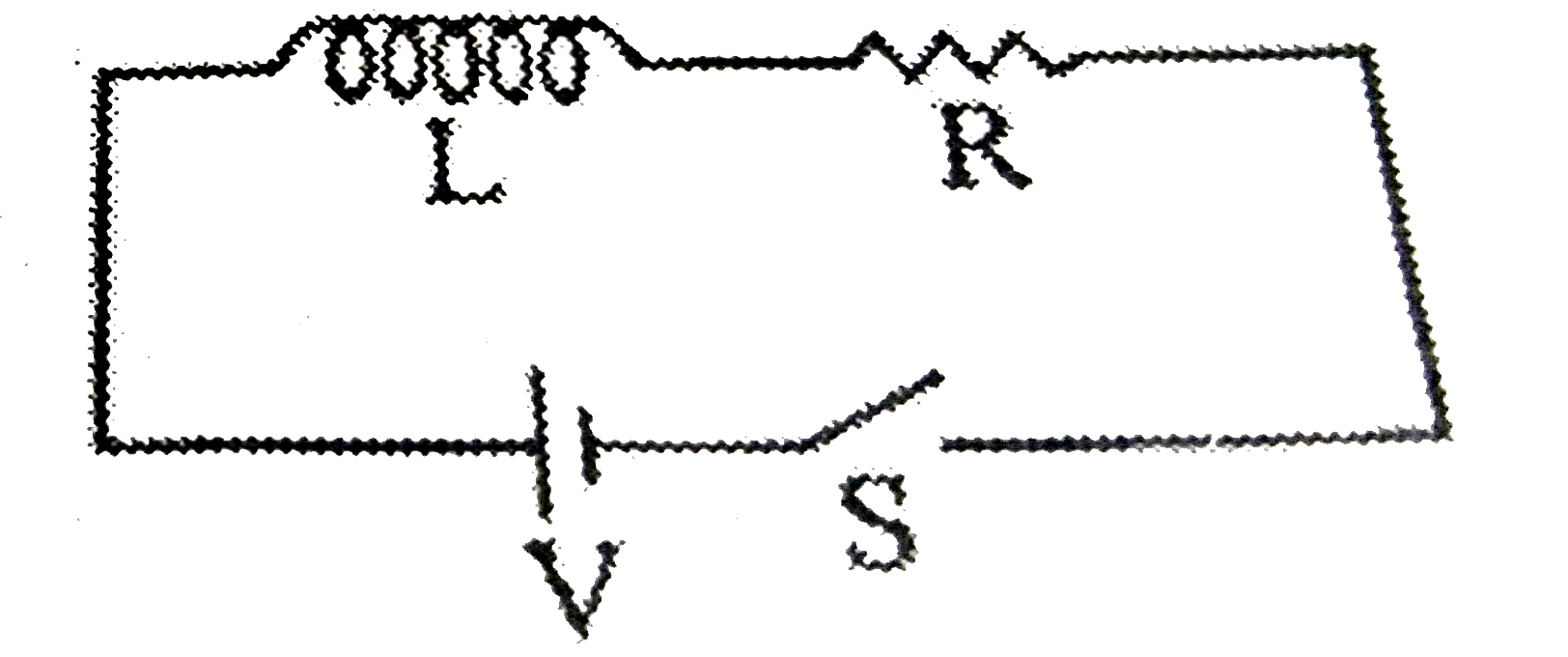
View SolutionIn the circuit as shown in figure the switch is closed at t=0.
At the instant of closing the switch
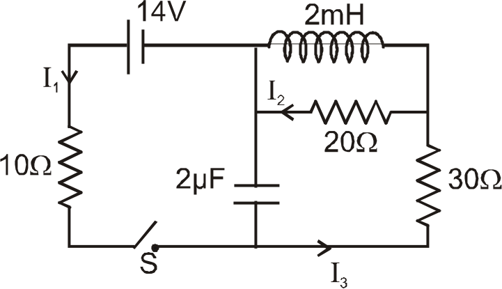
View SolutionIn the circuit shown, the switch is closed at t=0, the currents I1,I2 and I3 are
View Solution
