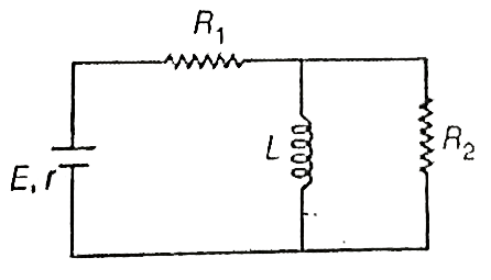
In the given circuit.

A
the current through the battery is 5A
B
P and Q are at the same potential
C
P is 2 V higher then Q
D
Q is 2 V higher then P
Video Solution
Text Solution
The correct Answer is:A, D
Resistors 2Ωand2Ω are in
series, and 2Ωand4Ω are
in series, then their resultant
are in parallel. Produce net resistance R=2.4Ω
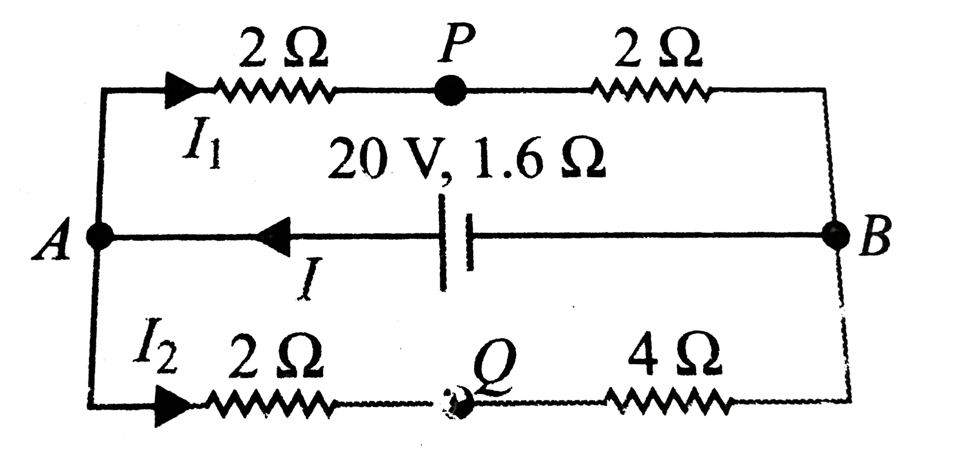
I=20r+R=201.6+2.4=5A
I1+I2=5A (i)
VAB=4I1=6I2or2I1=3I2 (ii)
From Eqs. (i) and (ii),I1=3A,I2=2A
VAVP=6V,VA−VQ=2I2=4V
Thus, VQ−VP=2V
|
Updated on:21/07/2023
Topper's Solved these Questions
- BOOK - CENGAGE PHYSICSCHAPTER - ELECTRIC CURRENT AND CIRCUITEXERCISE - Comprehension35videos
ELECTRIC CURRENT AND CIRCUIT
- BOOK - CENGAGE PHYSICSCHAPTER - ELECTRIC CURRENT AND CIRCUITEXERCISE - Interger8videos
ELECTRIC CURRENT AND CIRCUIT
- BOOK - CENGAGE PHYSICSCHAPTER - ELECTRIC CURRENT AND CIRCUITEXERCISE - Single Correct72videos
ELECTRIC CURRENT AND CIRCUIT
- BOOK - CENGAGE PHYSICSCHAPTER - ELECTRIC CURRENT & CIRCUITSEXERCISE - Kirchhoff s law and simple circuits15videos
ELECTRIC CURRENT & CIRCUITS
- BOOK - CENGAGE PHYSICSCHAPTER - ELECTRIC FLUX AND GAUSS LAWEXERCISE - MCQ s38videos
ELECTRIC FLUX AND GAUSS LAW
Similar Questions
Knowledge Check
- Question 1 - Select One
The output of the given circuit in Fig.
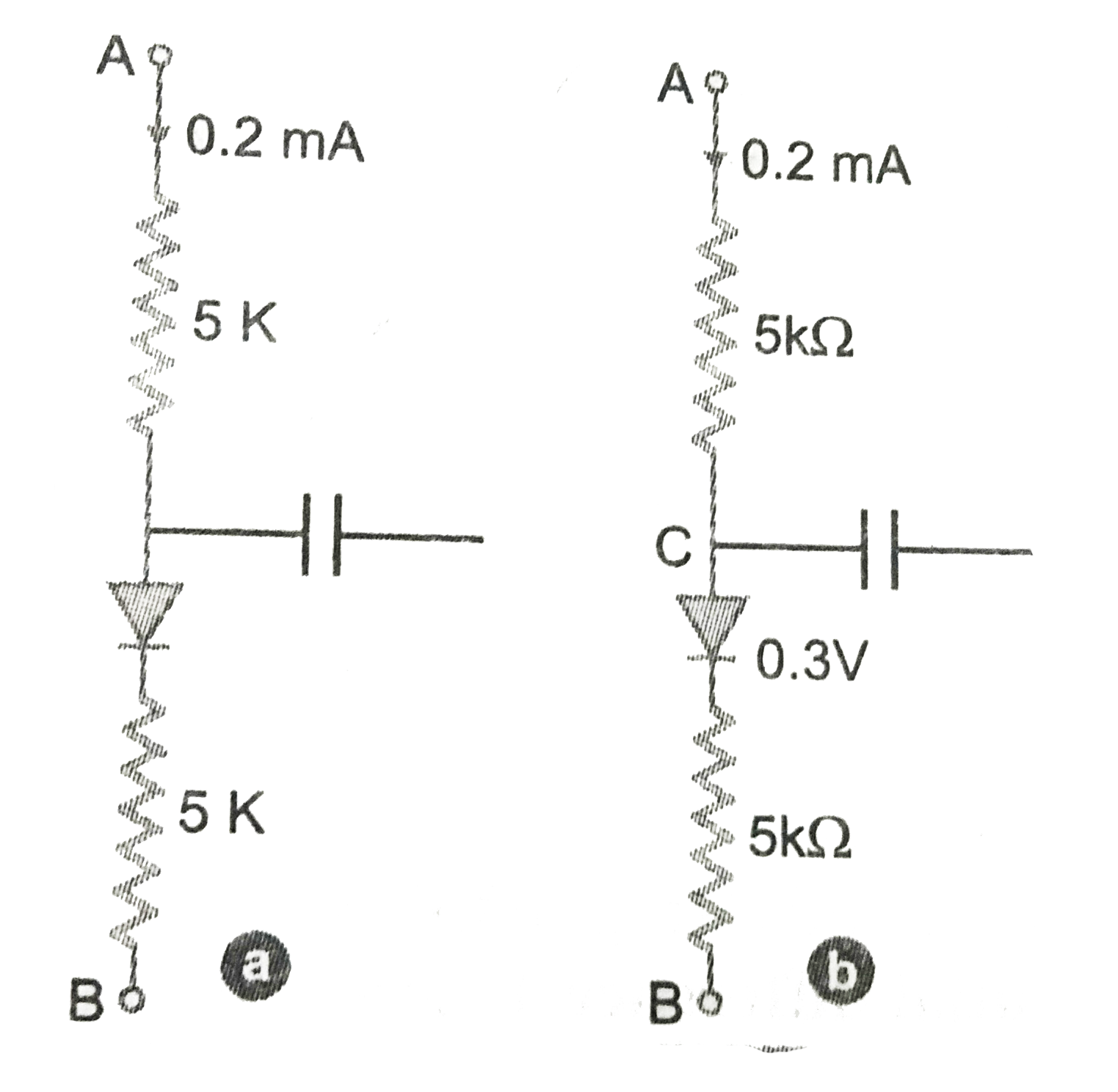 Awould be zero at all timesBwould be like a half wave rectifier with positive cycles in outputCwould be like a half wave rectifier with negative cycles in outputDwould be like that of a full wave rectifier
 - Question 2 - Select One
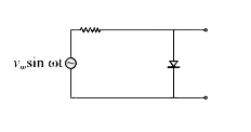
The output of the given circuit in Figure
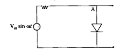 Awould be zero at all times.Bwould be like a half wave rectifier with positive cycles in output.Cwould be like a half wave rectifier with negative cycles in output.Dwould be like that of a full wave rectifier.
 - Question 3 - Select One
The output of the given circuit in Fig.
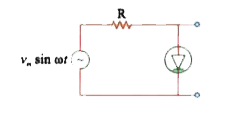 Awould be zero at all timesBwould be like a half-wave recifier with positive cycles in outputCwould be like a half-wave rectifer with negative cycles in outputDwould be like that of a full-wave rectifier.
The output of the given circuit in figure:
 View Solution
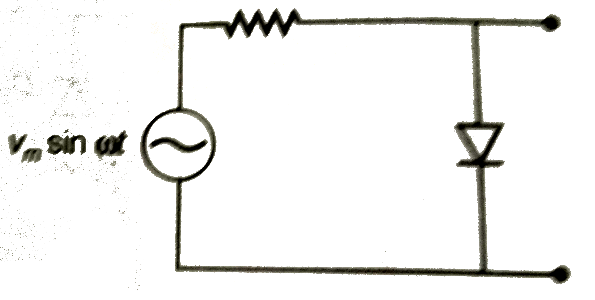
The output of the given circuit in figure given below,
 View Solution
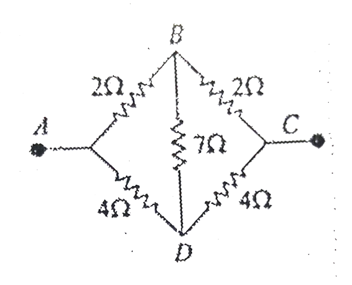
The equivalent resistance between A and C of the given circuit , is
 View Solution
Determine thte valur of time constan for the given circuit
 View Solution
The output for the given, circuit is
 View Solution


