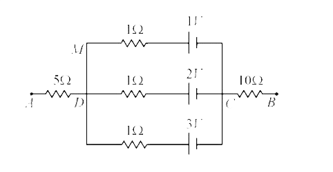
In the circuit shown in fig. some potential difference is applied between A and B. The equivalent resistance between A and B is R.

A
No current flows through the 5Ω resistor.
B
R=15Ω
C
R=12.5Ω
D
R=185Ω
Video Solution
Text Solution
The correct Answer is:A, D
 ,
,
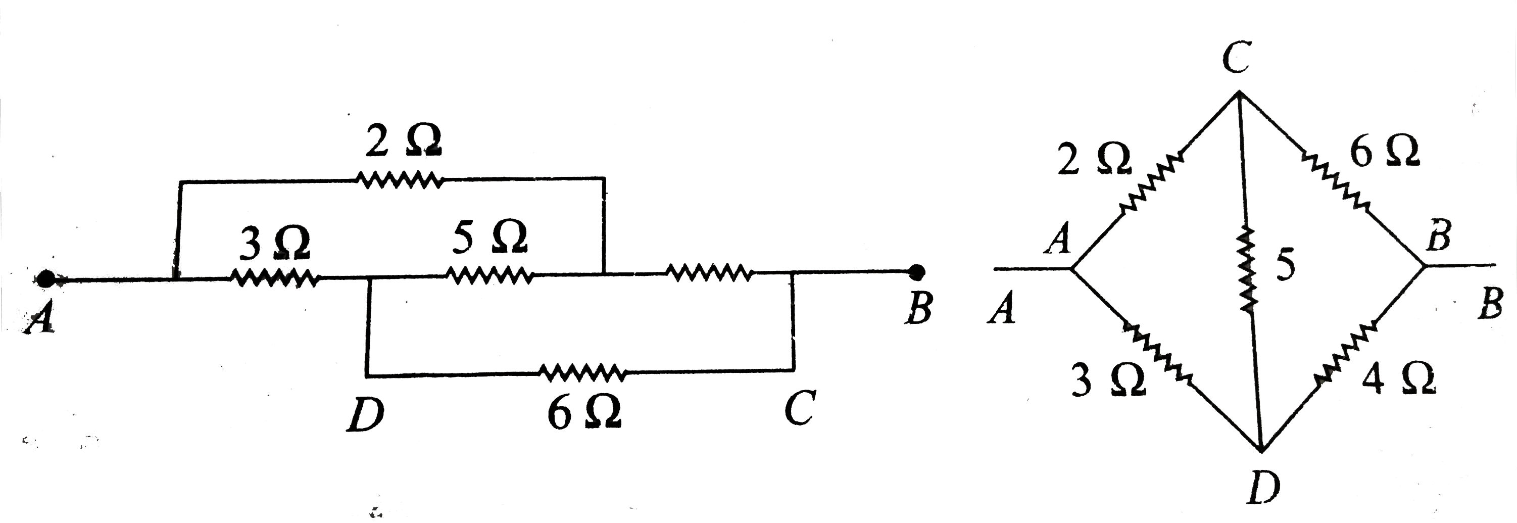
Rearrangement of the circuit as shwon in fig. gives a balanced wheatstone bridge, and no current flows through the
5Ω resistor. It can thus be removed from the circuit.
|
Updated on:21/07/2023
Topper's Solved these Questions
- BOOK - CENGAGE PHYSICSCHAPTER - ELECTRIC CURRENT AND CIRCUITEXERCISE - Comprehension35videos
ELECTRIC CURRENT AND CIRCUIT
- BOOK - CENGAGE PHYSICSCHAPTER - ELECTRIC CURRENT AND CIRCUITEXERCISE - Interger8videos
ELECTRIC CURRENT AND CIRCUIT
- BOOK - CENGAGE PHYSICSCHAPTER - ELECTRIC CURRENT AND CIRCUITEXERCISE - Single Correct72videos
ELECTRIC CURRENT AND CIRCUIT
- BOOK - CENGAGE PHYSICSCHAPTER - ELECTRIC CURRENT & CIRCUITSEXERCISE - Kirchhoff s law and simple circuits15videos
ELECTRIC CURRENT & CIRCUITS
- BOOK - CENGAGE PHYSICSCHAPTER - ELECTRIC FLUX AND GAUSS LAWEXERCISE - MCQ s38videos
ELECTRIC FLUX AND GAUSS LAW
Similar Questions
Knowledge Check
- Question 1 - Select One
Equivalent resistance between A and B in Fig. is
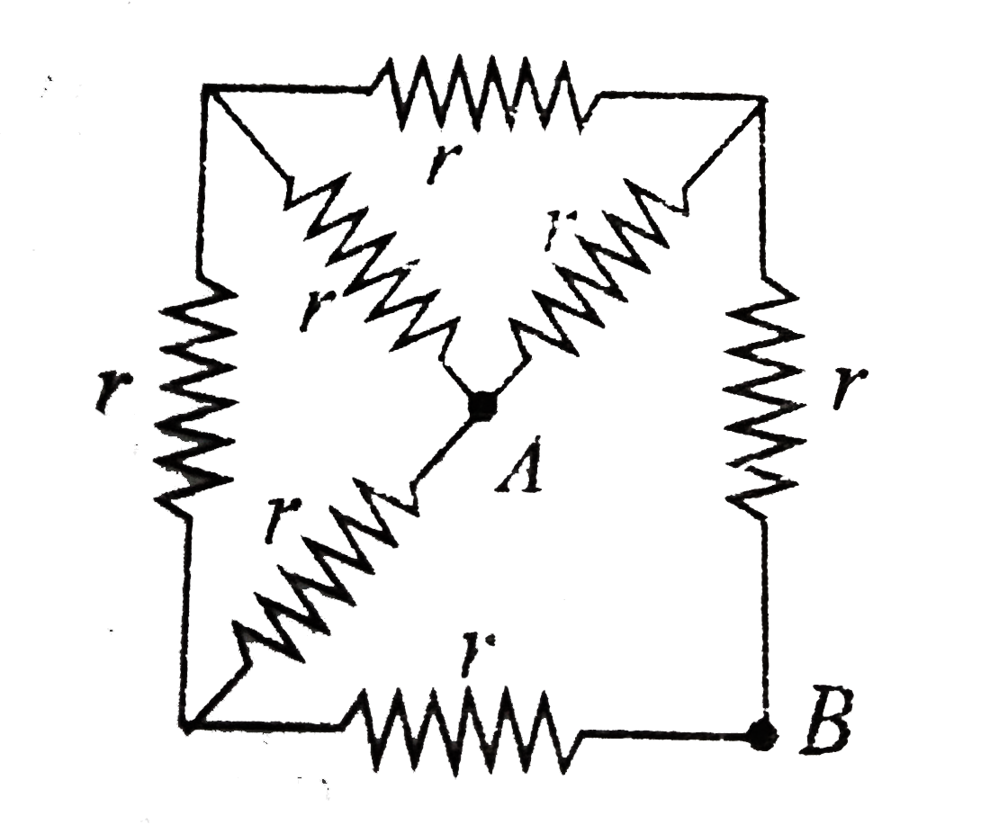 A8r/7B7r/8C3r/4Dr
 - Question 2 - Select One or More
In the circuit shown, some potential difference is applied between A and B If C is joined to D
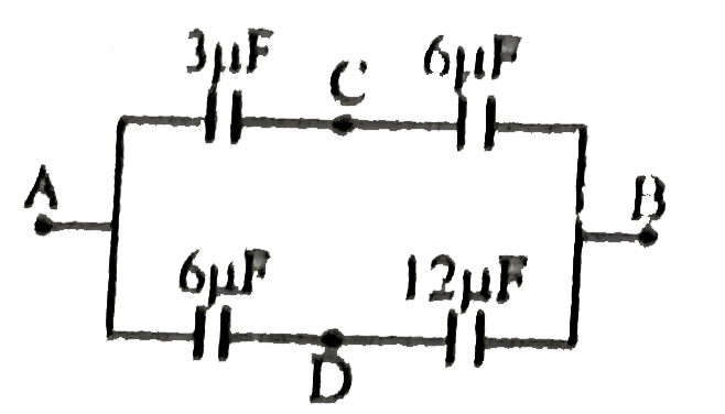 Ano charge will flow between C and DBsome charge will flow between C and DCthe equivalent capacitance between A and B will not changeDthe equivalent capacitance between A and B will change.
 - Question 3 - Select One
In the circuit shown in figure potential difference between A and B is
 A30 VB60 VC10 VD90 V
In the circuit shown in the following figure some potential difference is applied between A and B . IF C is joined to D,
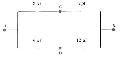 View Solution
For the circuit shown in fig. the equivalent resistance between A and C is
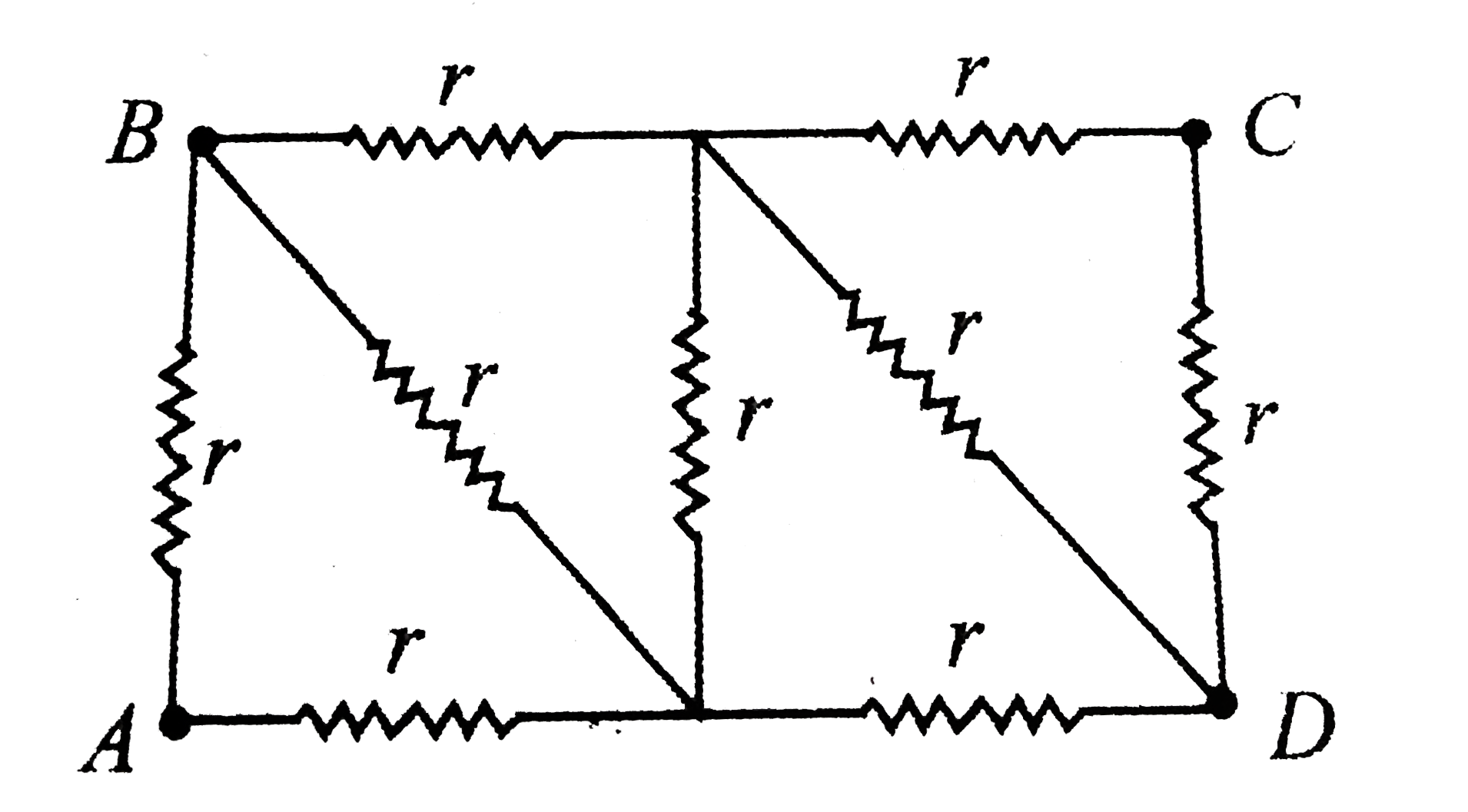 View Solution
In the circuit shown, the potential difference across the 3μF capacitor is V and the equivalent capacitance between A and B is C Then:
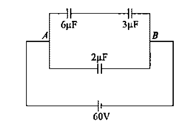 View Solution
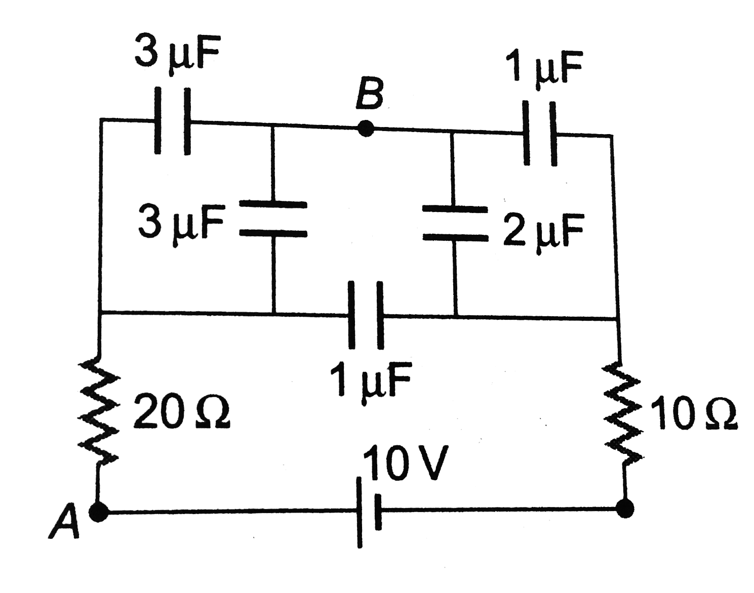
In the circuit shown in figure potential difference between the points A and B in the steady state is
 View Solution
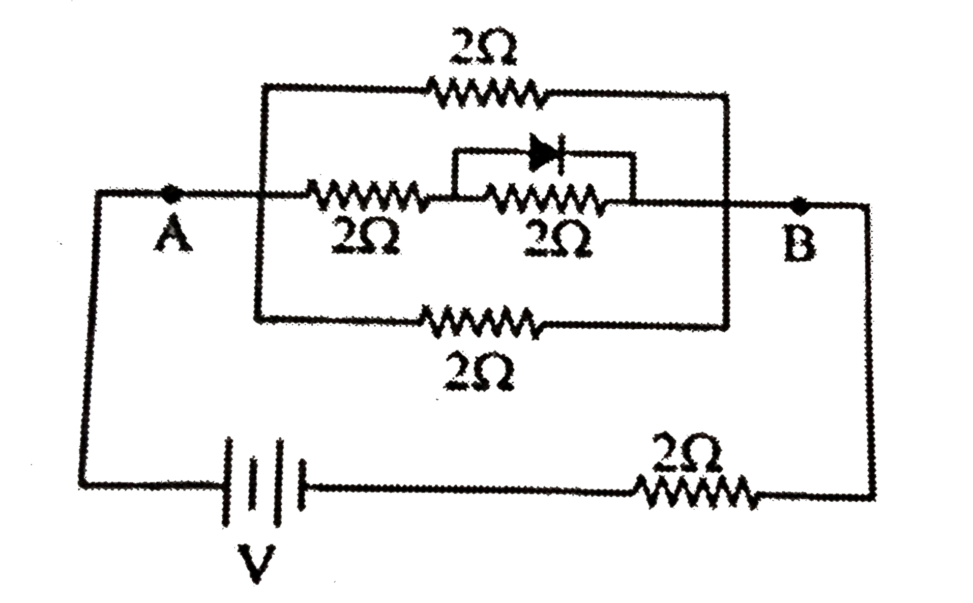
In the circuit shown in figure , the diode is ideal The potential difference between A and B is
 View Solution


