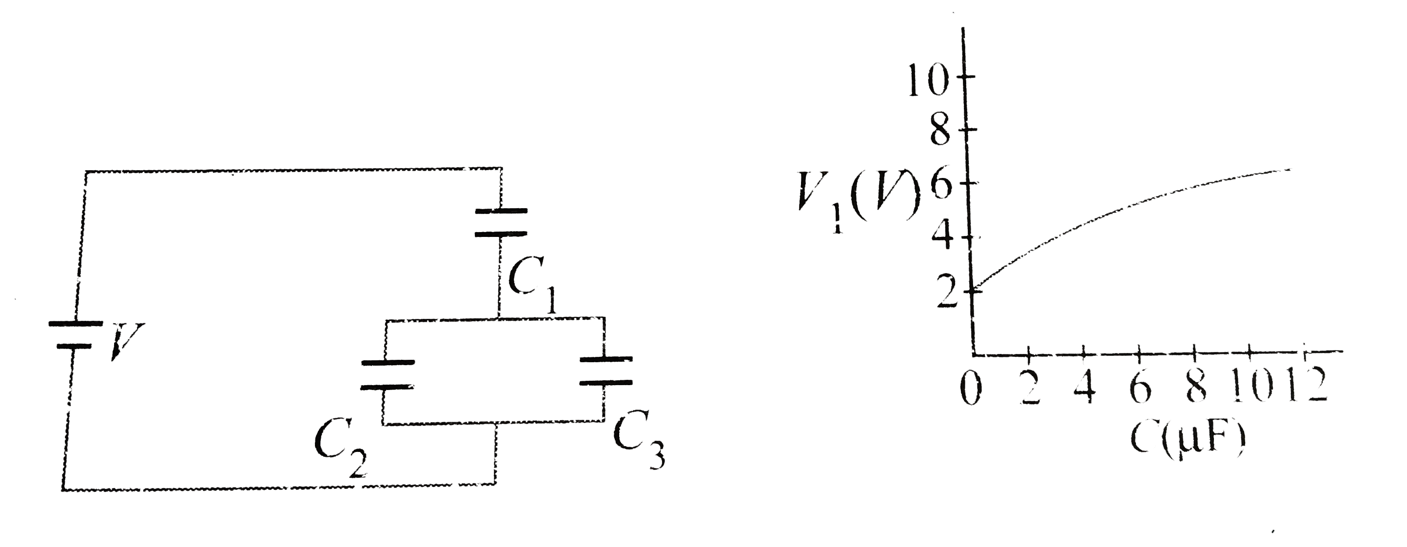
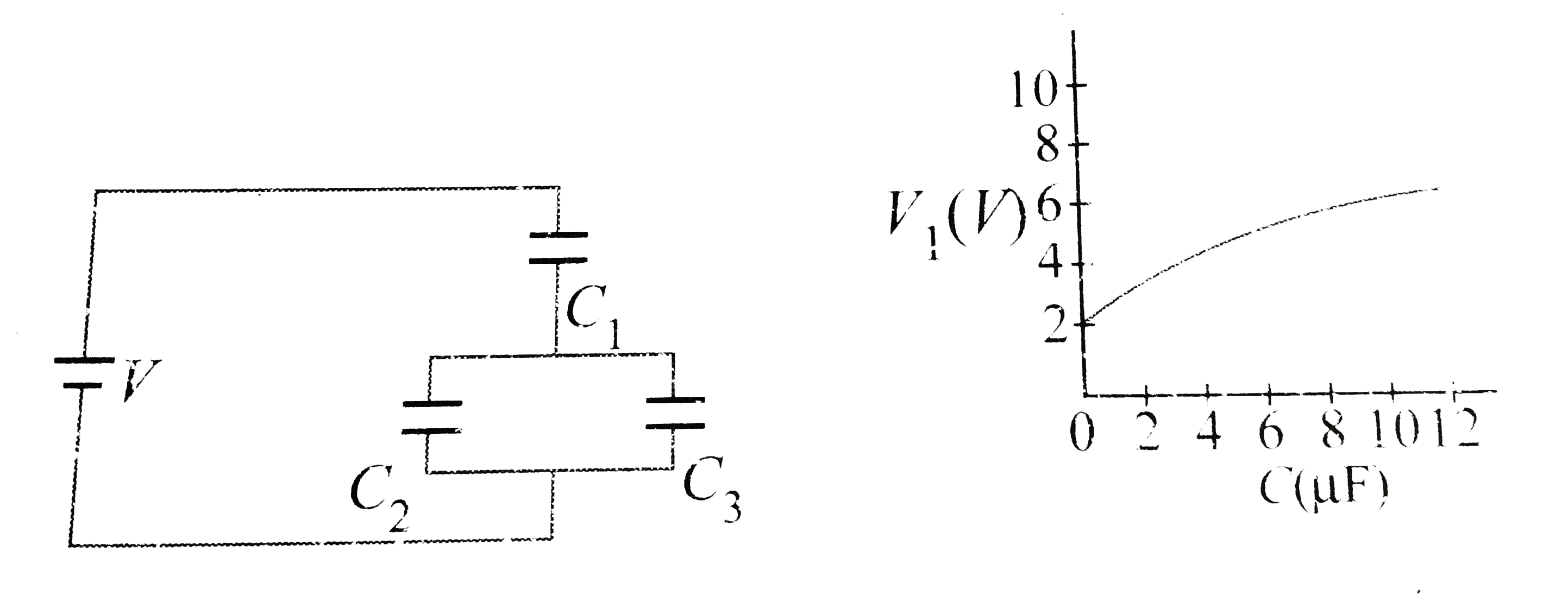
Capacitor C3 in the circuit is a variable capacitor (its capacitance can be varied). C1andC2 are of fixed values. Graph is plotted between potential difference V1 (across capacitor C1) versus C3. Electric potential V1 approches on asymptote of 10 V as C3∝∞.
 ,
,
Relation between C1andC2 is
C1=C2
C1=4C2
4C1=C2
any relation
The correct Answer is:C
When C3→∞ it means distance between the plates of C3 is zero or both plates will be at the same potential then C2 will be shorted entire pontential V will ber across C1 hence V=V1=10V
From graphs when C3=0,V1=2V.SoC3 will act like open switch C1 and C2 will be in series potential different across C2 is V2=10−V1
=8V
q=C1V1=C2V2 or C12=C28 or C1=4C2
V1=4V,V2=10−4=6V
q=C1V1=(C2+C3)V2
or C14=(C2+C3)6 or 16C2=6C2+6C3
or C3=5C2/3
Topper's Solved these Questions
- MISCELLANEOUS VOLUME 3BOOK - CENGAGE PHYSICSCHAPTER - MISCELLANEOUS VOLUME 3EXERCISE - Interger Answer type
20 Videos
- MISCELLANEOUS VOLUME 3BOOK - CENGAGE PHYSICSCHAPTER - MISCELLANEOUS VOLUME 3EXERCISE - Fill in the blanks
10 Videos
- MISCELLANEOUS VOLUME 3BOOK - CENGAGE PHYSICSCHAPTER - MISCELLANEOUS VOLUME 3EXERCISE - Assertion and Reason Type
8 Videos
- MECHANICAL PROPERTIES OF SOLIDSBOOK - CENGAGE PHYSICSCHAPTER - MECHANICAL PROPERTIES OF SOLIDSEXERCISE - Question Bank
4 Videos
- MISCELLANEOUS VOLUME 5BOOK - CENGAGE PHYSICSCHAPTER - MISCELLANEOUS VOLUME 5EXERCISE - Integer
12 Videos
Similar Questions
Capacitor C3 in the circuit is variable capacitor (its capacitance can be varied). Graph is plotted between potential difference V1 (across capacitor C1) versus C3.
Electric potential V1 approaches on asymptote of 10 volts as C3→∞
The ratio of the capacitance C1C2 will be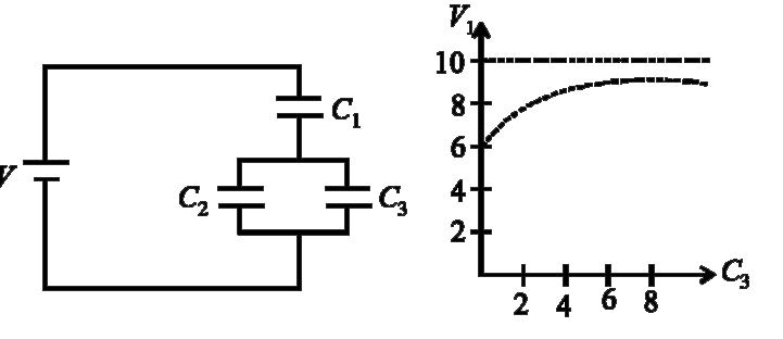
View SolutionCapacitor C3 in the circuit is variable capacitor (its capacitance can be varied). Graph is plotted between potential difference V1 (across capacitor C1) versus C3.
Electric potential V1 approaches on asymptote of 10 volts as C3→∞
0The value of C3 for which potential difference across C1 will become 8V, is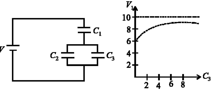
View Solution
Knowledge Check
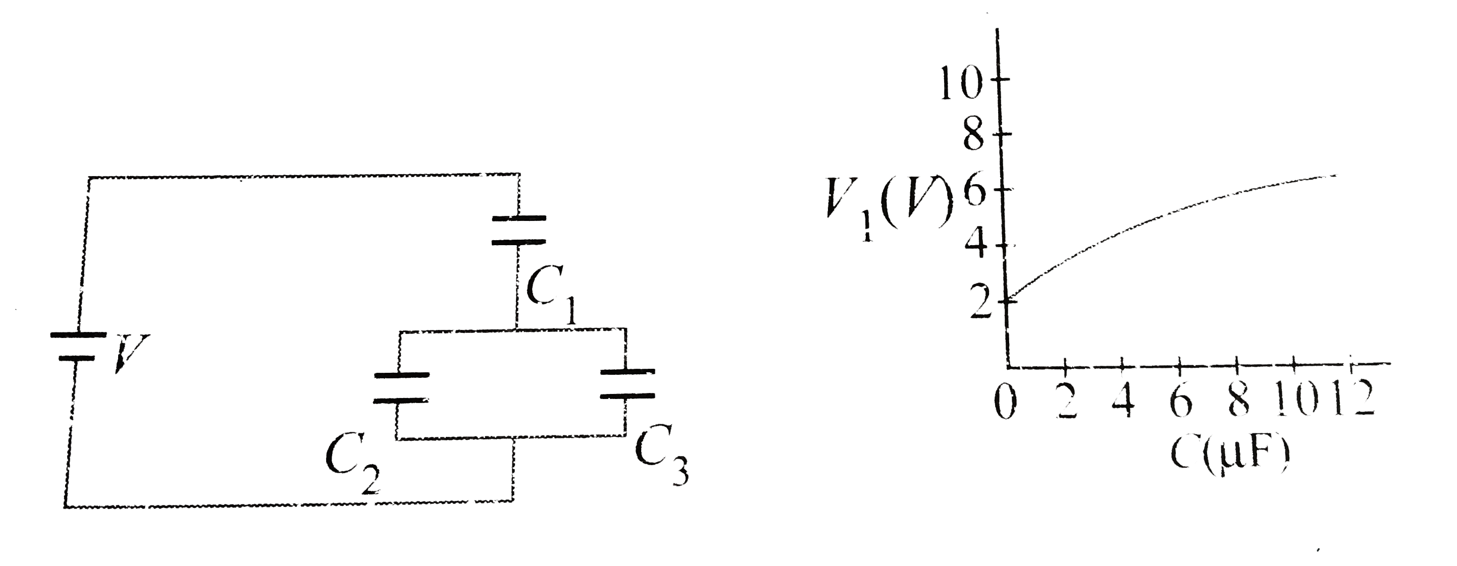
Capacitor C3 in the circuit is a variable capacitor (its capacitance can be varied). C1andC2 are of fixed values. Graph is plotted between potential difference V1 (across capacitor C1) versus C3. Electric potential V1 approches on asymptote of 10 V as C3∝∞.
 ,
,
When V1=4Vm then C3 is equal toA5C2/2B5C1/3C5C2/3Dnone of theseCapacitor C3 in the circuit is a variable capacitor (its capacitance can be varied). C1andC2 are of fixed values. Graph is plotted between potential difference V1 (across capacitor C1) versus C3. Electric potential V1 approches on asymptote of 10 V as C3∝∞.
 ,
,
The electric potential V across the battery is equal toA10VB12VC16VD20VCapacitor C3 in the circuit is a veriable capacitor (its capacitance can be varied). Group is plotted between potential difference V1 (across capacitor C1) versus C3. Electric potential V1 approaches to 10 V as C3→∞. Given that C1+C2=10μF

EMF of the battery is equal toA10 VB12 VC16 VD20 V
Capacitor C3 in the circuit is variable capacitor (its capacitance can be varied). Graph is plotted between potential difference V1 (across capacitor C1) versus C3.
Electric potential V1 approaches on asymptote of 10 volts as C3→∞
The value of C3 for which potential difference across C1 will become 8V, is
View SolutionCapacitor C3 in the circuit is variable capacitor (its capacitance can be varied). Graph is plotted between potential difference V1 (across capacitor C1) versus C3.
Electric potential V1 approaches on asymptote of 10 volts as C3→∞
The ratio of energy stored in capacitorC1 to that of total energy whenC3→∞ is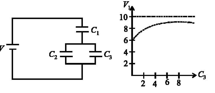
View SolutionCapacitor C3 in the circuit is a veriable capacitor (its capacitance can be varied). Group is plotted between potential difference V1 (across capacitor C1) versus C3. Electric potential V1 approaches to 10 V as C3→∞. Given that C1+C2=10μF

EMF of the battery is equal to
View SolutionCapacitor C3 in the circuit is a variable capacitor (its capacitance can be varied). Graph is plotted between potential difference V1 (across capacitor C1) versus C3. Electric potential V1 approaches to 10 V as C3→∞. Given that C1+C2=10μF

The capacitance of the capacitor C1 value
View SolutionCapacitor C3 in the circuit is a veriable capacitor (its capacitance can be varied). Group is plotted between potential difference V1 (across capacitor C1) versus C3. Electric potential V1 approaches to 10 V as C3→∞. Given that C1+C2=10μF

The capacitance of the capacitor C1 value
View Solution
