In the circuit shown, all capacitors are identical. Initially, the switch is open and the capacitor marked C1 is the only one charged to a value Q0. After the switch is closed and the equilibrium is reestablished, the charge on the capacitor marked C1 is Q. Find the ratio initial change to final charge in capacitor C1.
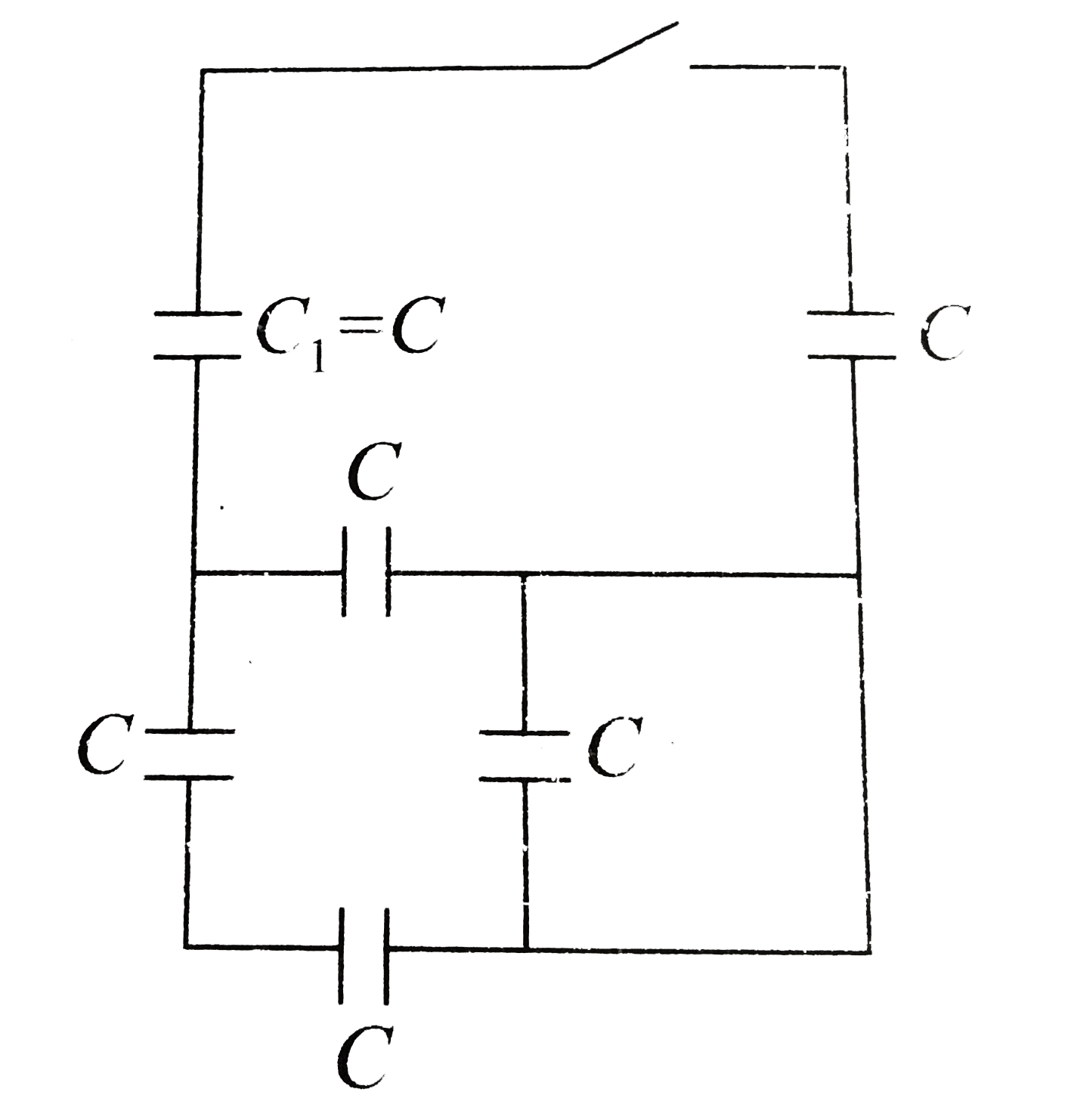
We begin with the circuit given, assigining names to each identical capacitor. C1 begins with an unknown initial charge Q03 and achieves a charge Q after the circuit is connected and has re-established equilibrium.

As C3 is clearly shorted, the potential difference across its plates is 0, and as such the capacitor will contain no charge and will not afect the circuit We can therefore remove it from the schematic. This simplified circuit can be broken down into even simpler equivalne tcircuits. Leaving C1 where it is, and recognizing C3 and C4 in series with each other *yielding an equivalent capacitance of 1/2C), and together in parallel with C4, Acknowledging the combined capacitors are equal, C456 must have an equivalent capacitance of 3/2C, As C456 is simply in series with C2, the resultant equivalent circuit has simply one capacitor (C2456) in series with C1, where C456 must have an equivalent capacitance of 3/5C,
Since Q=CV,V1=Q/C
where V1 is the potential difference across C1,V2456 is the potential difference across C2456, and Q is the charge on C2456 For equilibrium conditions, V1=V2. Therefore,
Q/C=5Q/C,3CQ=5CQ
Q=(3/5)Q
by the conservation of charge,
Q0=Q+Q=Q+(3/5)Q=(8/5)Q.
The initial charge on the capacitor was 8/5 of the final charge on the capacitor after the switch was closed.

Topper's Solved these Questions
- MISCELLANEOUS VOLUME 3BOOK - CENGAGE PHYSICSCHAPTER - MISCELLANEOUS VOLUME 3EXERCISE - Fill in the blanks
10 Videos
- MISCELLANEOUS VOLUME 3BOOK - CENGAGE PHYSICSCHAPTER - MISCELLANEOUS VOLUME 3EXERCISE - True and False Type
5 Videos
- MISCELLANEOUS VOLUME 3BOOK - CENGAGE PHYSICSCHAPTER - MISCELLANEOUS VOLUME 3EXERCISE - Comprehension Type
94 Videos
- MECHANICAL PROPERTIES OF SOLIDSBOOK - CENGAGE PHYSICSCHAPTER - MECHANICAL PROPERTIES OF SOLIDSEXERCISE - Question Bank
4 Videos
- MISCELLANEOUS VOLUME 5BOOK - CENGAGE PHYSICSCHAPTER - MISCELLANEOUS VOLUME 5EXERCISE - Integer
12 Videos
Similar Questions
Knowledge Check
In the given figure switch is open initially and capacitor C2 is unchanged
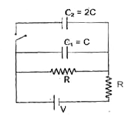
Charge on C2 just after closing the switch isACV2BCV3CCV4DCV8In the circuit shown in fig. when the switch is closed, the capacitor charges with a time constant
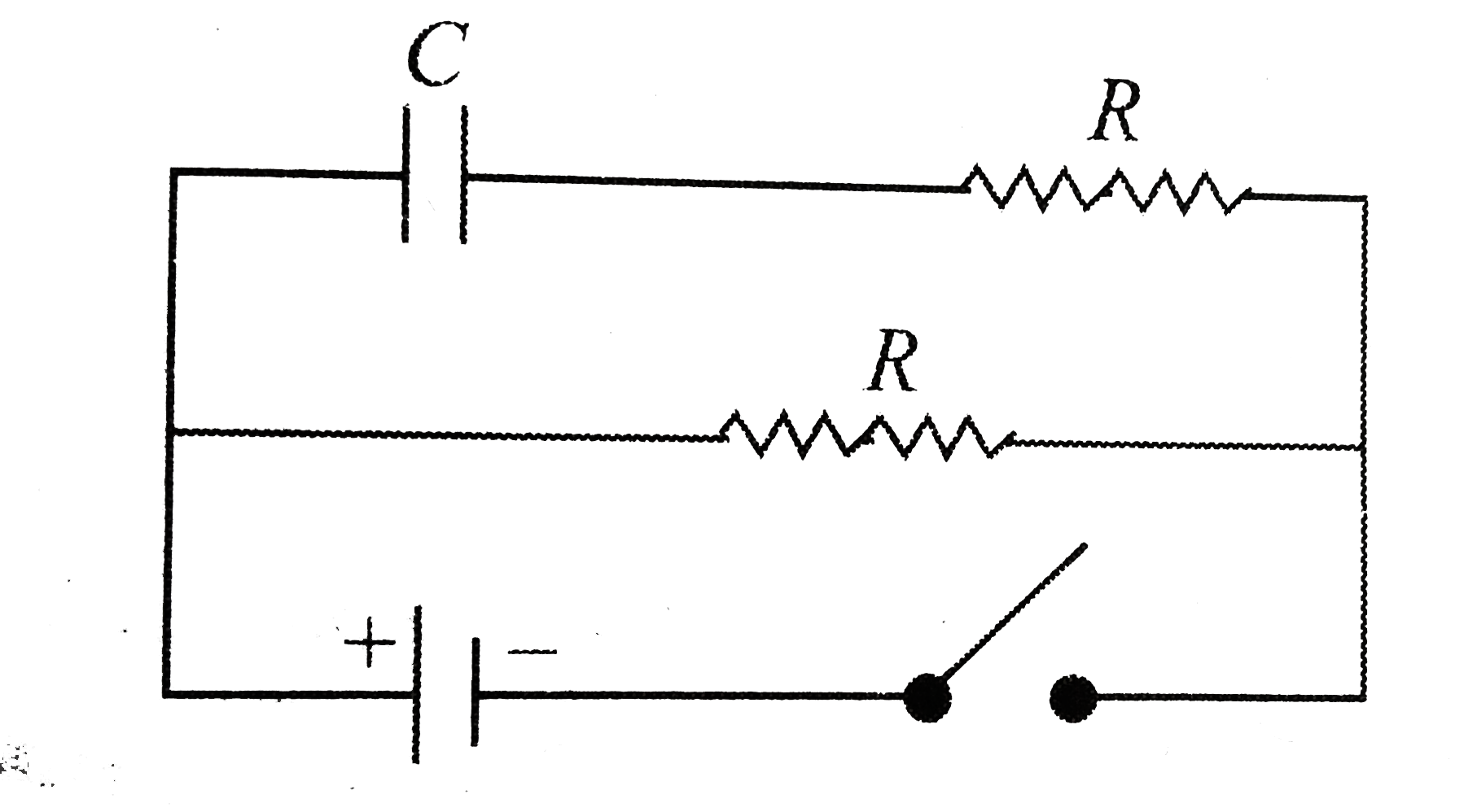 ARCB2 RCC12RCDRC log2
In the circuit shown, the capacitor C1 is initially charged with charge q0. The switch S is closed at time t = 0 . The charge on C2 after time t is
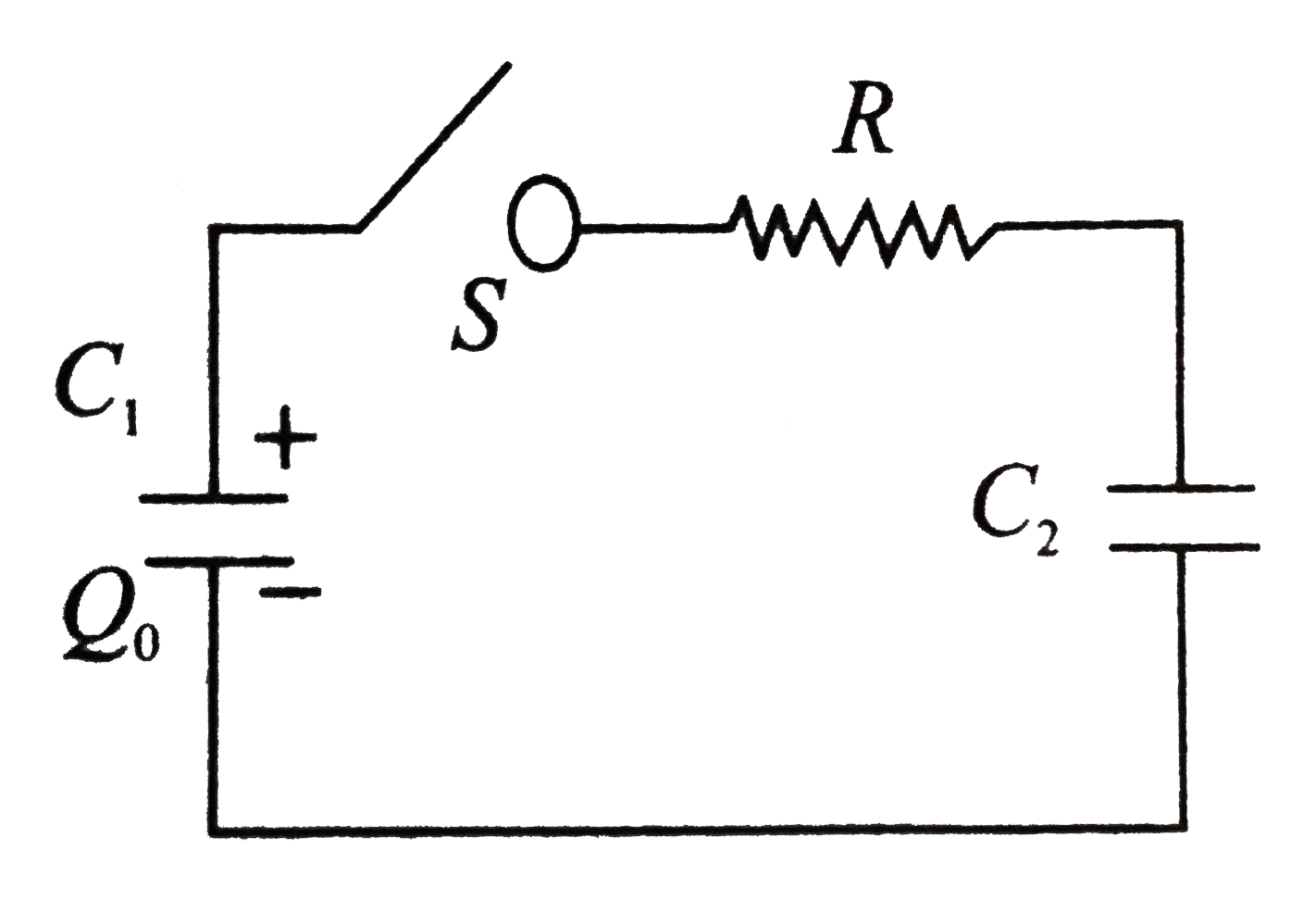 Aq0C1C1+C2(1−e−t(C1+C2)C1C2R)Bq0C2C1+C2(1−e−t(C1+C2)C1C2R)Cq0C1C1+C2(1−e−tC2R)Dq0C2C1+C2(1−e−tC2R)
Initially the capacitor is uncharged find the charge on capacitor as a function of time, if switch is closed at t=0.
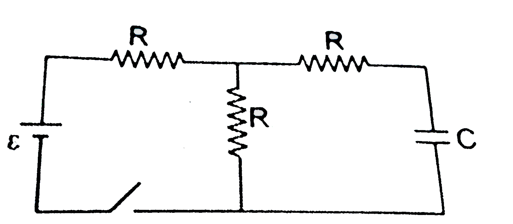
View SolutionIn the circuit shown in fig. when the switch is closed, the capacitor charges with a time constant

View SolutionIn the circuit shown, the capacitor C1 is initially charged with charge q0. The switch S is closed at time t = 0 . The charge on C2 after time t is

View SolutionFind out current in the circuit and charge on capacitor which is initially uncharged in the following situations
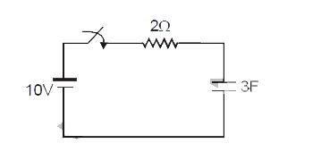
Just after the switch is closed
View SolutionThe capacitor of capacitance C in the circuit shown in fully charged initially. Resistance is R.–
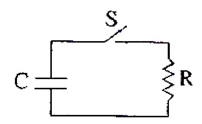
After the switch S is closed, the time taken to reduce the stored energy in the capacitor to half its initial value is
View Solution
