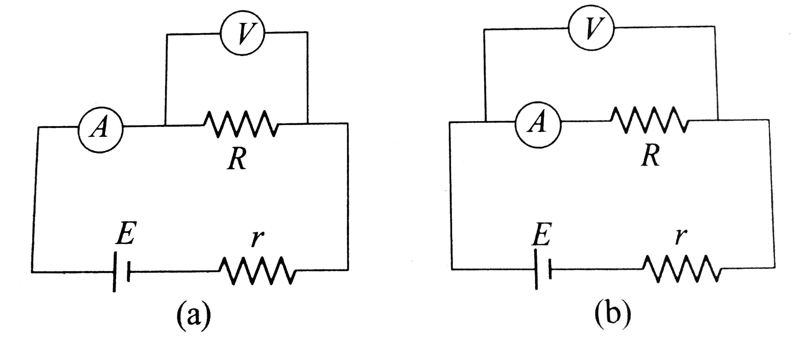
The actual value of resistance R, shown in the figure is . This is measured in an experiment as shown using the standard formula , where V and I are the readings of the voltmeter and ammeter, respectively. If the measured value of R is 5% less, then the internal resistance of the voltmeter is
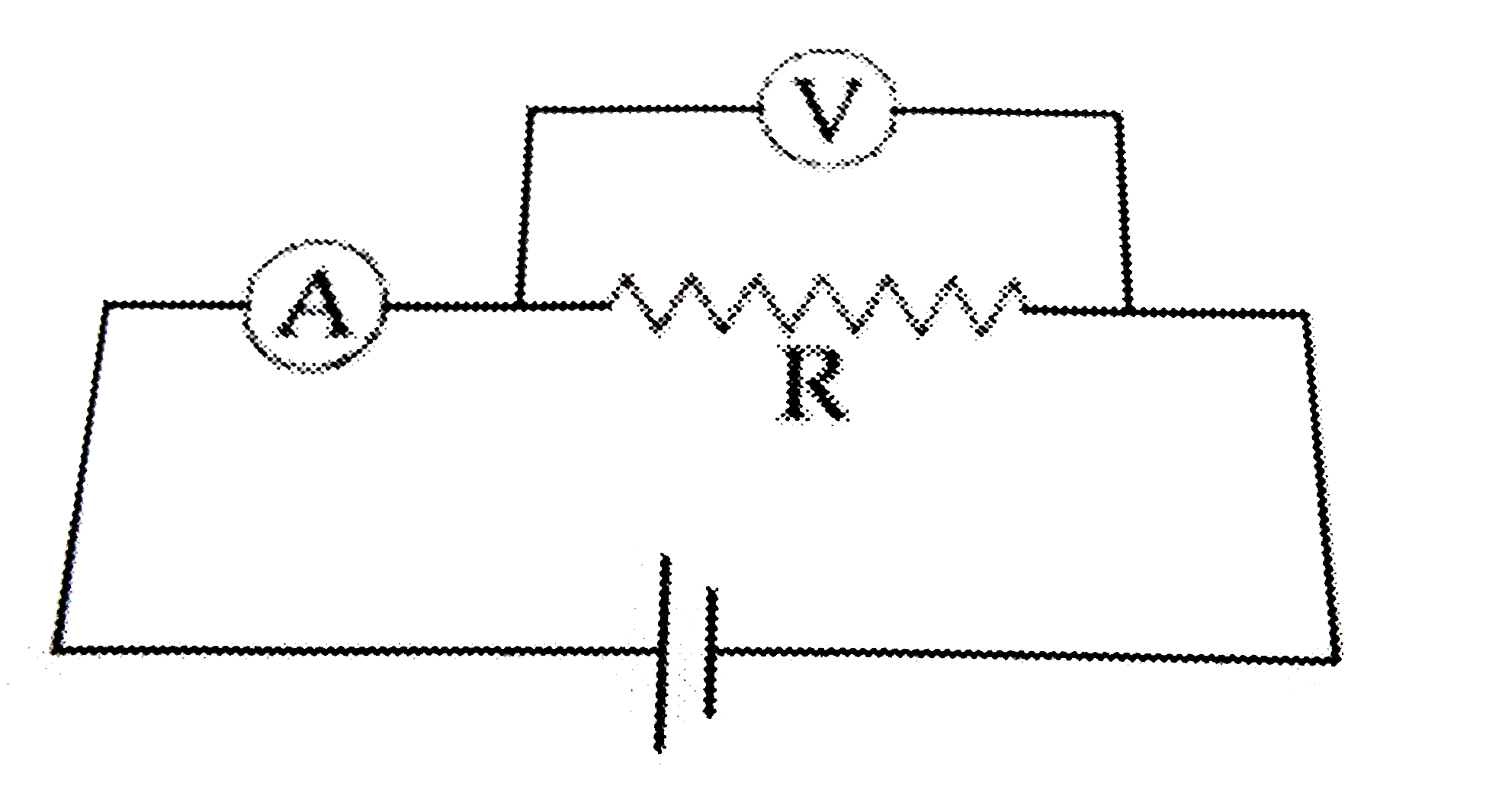
Step by step video & image solution for The actual value of resistance R, shown in the figure is 30 Omega. This is measured in an experiment as shown using the standard formula R = (V)/(I), where V and I are the readings of the voltmeter and ammeter, respectively. If the measured value of R is 5% less, then the internal resistance of the voltmeter is by Physics experts to help you in doubts & scoring excellent marks in Class 12 exams.
Updated on:21/07/2023Topper's Solved these Questions
Similar Questions
In the adjoining circuit diagram, the readings of ammeter and voltmeter are 2 A and 120 V, respectively. If the value of R is 75Ω, then the voltmeter resistance will be
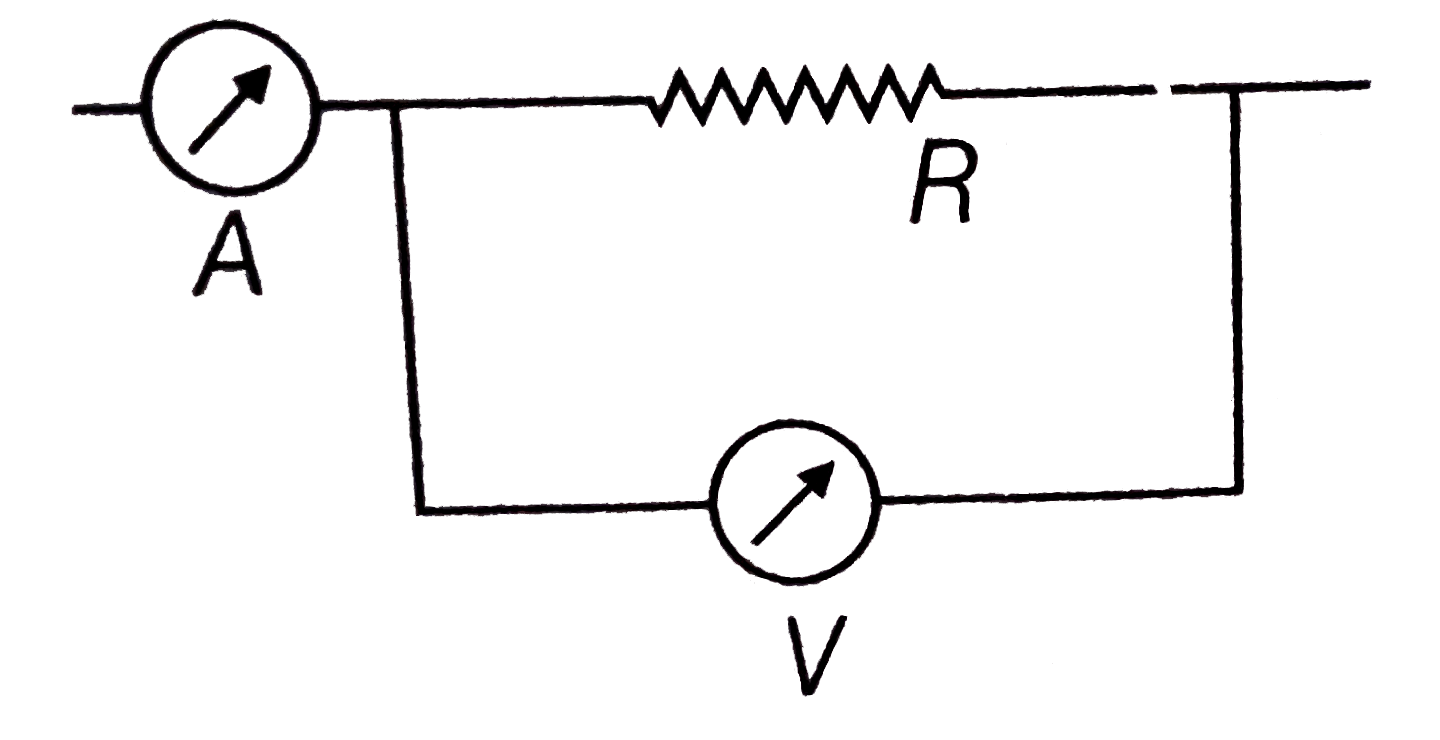
View SolutionLet V and I be the readings of the voltmeter and the ammeter respectively as shown in the figure. Let RV and RA be their corresponding resistancce Therefore,
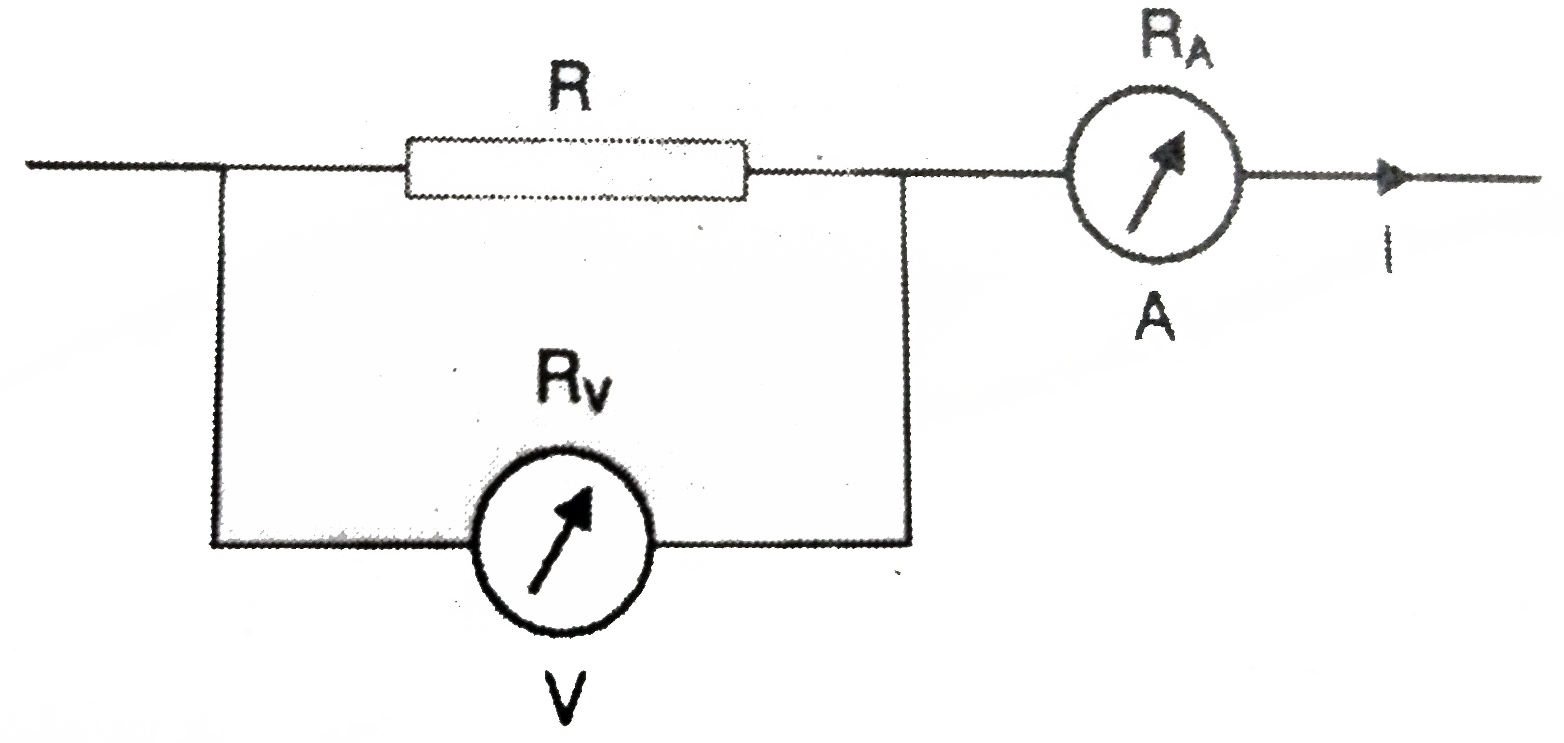
View SolutionIn the circuit figure, the voltmeter reads 30 V. The resistance of the voltmeter is
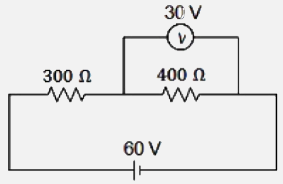
View SolutionThe value of resistance of an unknown resistor is calculated using the formula R=V/I where V and I are the readings of the voltmeter and the ammeter, respectivley. Consider the circuits below. The internal resistances of the voltmeter and the ammeter (RVandRG,respectively) are finite and nonzero.
 ,
,
Let RAandRB be the calculated values in the two cases A and B , respectively.
If the resistance of voltmeter is RV=1kΩ and the percentage error in the measurement of R (the value of R is nearly 10Ω)is
View SolutionDetermine the resistance r if an ammeter shows a current of I=5A and a voltmeter 100V. The internal resistance of the voltmeter is R=2,500Ω
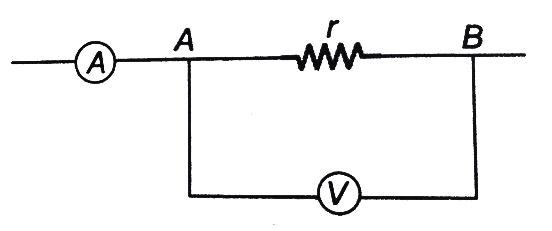
View SolutionIn the circuit shown the reading of ammeter and voltmeter are 4A and 20V respectively. The meters are non ideal, then R ia

View SolutionThe ammeter A reads 2A and the voltmeter V reads 20V, the value of resistance R is (Assuming finite resistance's of ammeter and voltmeter)
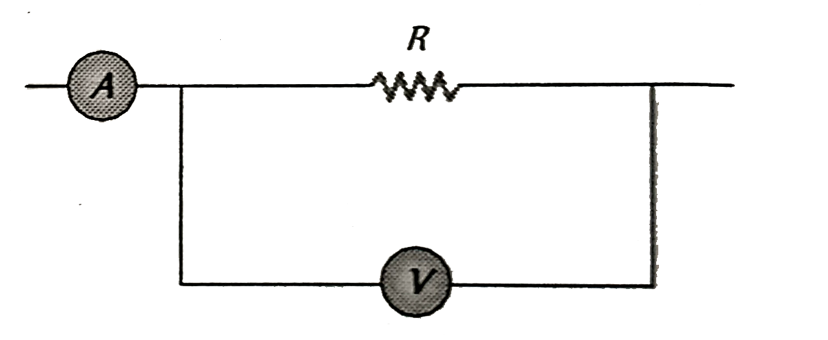
View SolutionWhich of the following circuits gives the correct value of resistance, when computed by using R=(V/I) where V and I are voltmeter and ammeter reading, respectively? The meters are not ideal.
View SolutionIn the circuit shown alongside, the ammeter and the voltmeter redings are 3A and 6V, respectively. Then, the value of the resistance R is

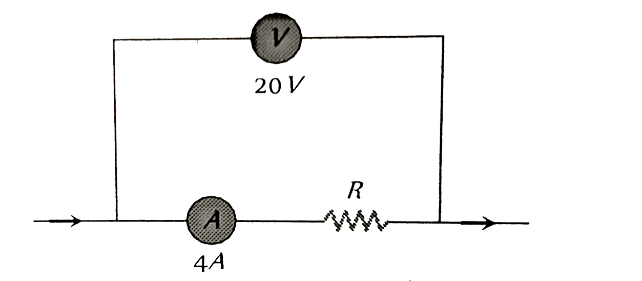
View SolutionIn the diagram shown, the reading of voltmeter is 20 V and that of ammeter is 4 A . The value of R should be (Consider given ammeter and voltmeter are not ideal)
View Solution
