In the circuit diagram shown in figure, initially switch S is opened and the circuit is in steady state. At time t=0, the switch S is closed and the new steady state is reached after some time. Choose the correct option(s)
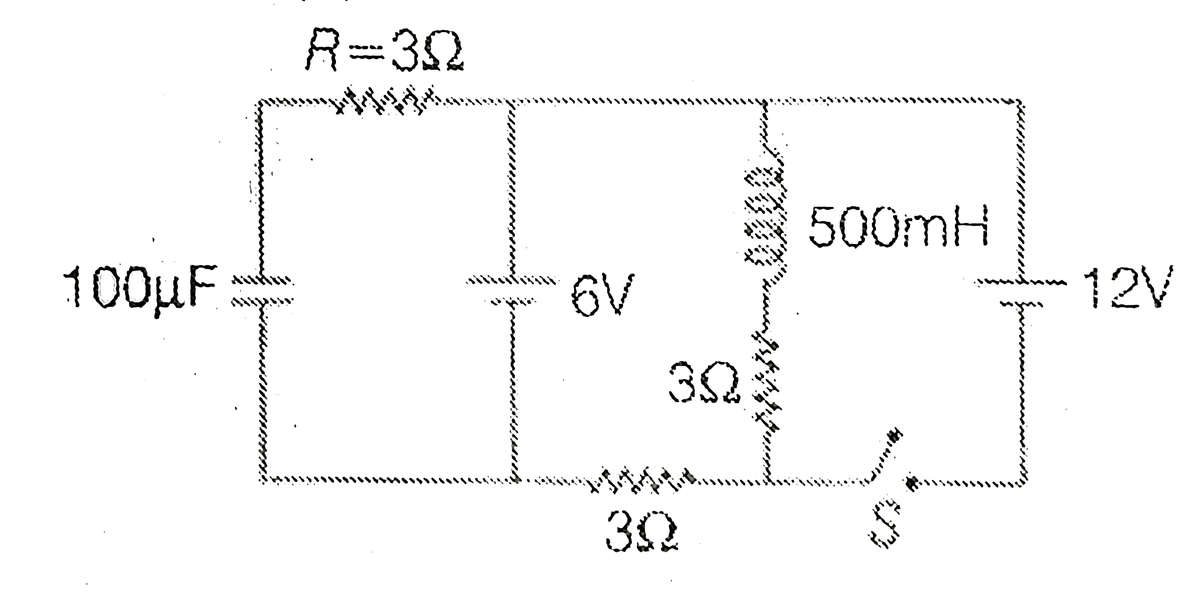
Current in the indcutor when the circuit reaches the new steady state is 4A.
The net change in the magnitic flux is the inductor is 1.5Wb
The net change in the magnetic flux in the conductor is 9volt when the circuit reaches the new steady state.
The charge stored in the capacitor in the new steady state is 1.2mC
The correct Answer is:A, B
Similar Questions
Knowledge Check
In the circuit shown in figure, switch S is initially closed and S is open. Find V-V
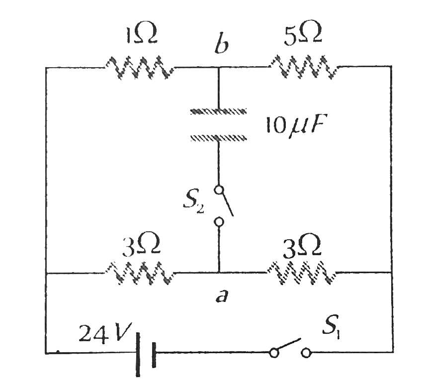 A4VB8VC12VD16V
In the circuit as shown in figure the switch is closed at t=0.
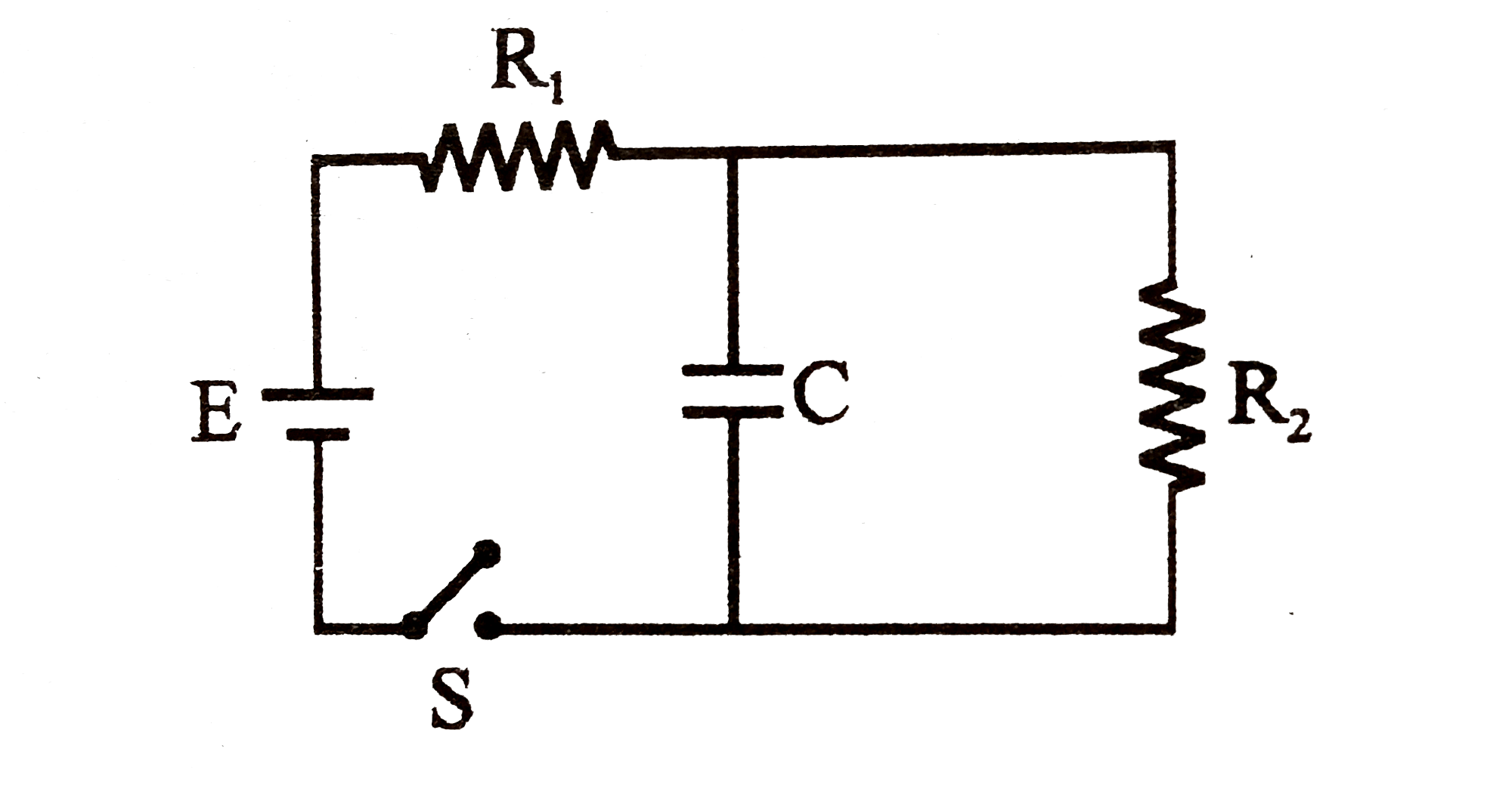
A long time after closing the switchAvoltage drop across the capacitor is EBcurent through the battery is E/R1+R2Cenegru stores in the capacitor is
12C(R2ER1+R2)2Dcurrent through the capacitor becomes zeroIn the circuit shown in the figure, switch S is closed at time t=0. Select the correct statements.
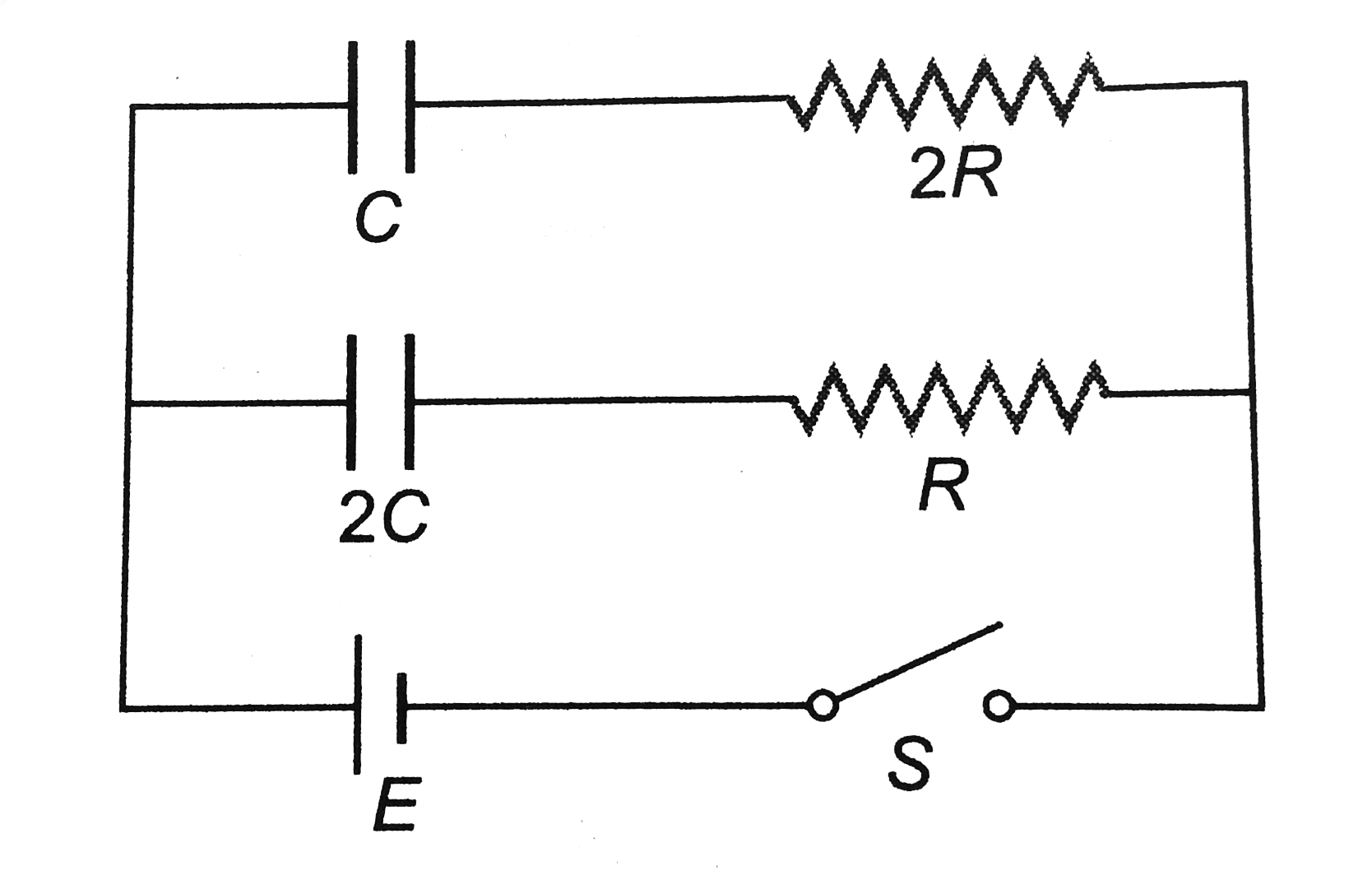 ARate of increase of charge is same in both the capacitorsBRatio of charge stored in capacitors C and 2C at any time t would be 1:2CTime constants of both the capacitors are equalDSteady state chares on capacitors C and 2C are in the ratio of 1:2
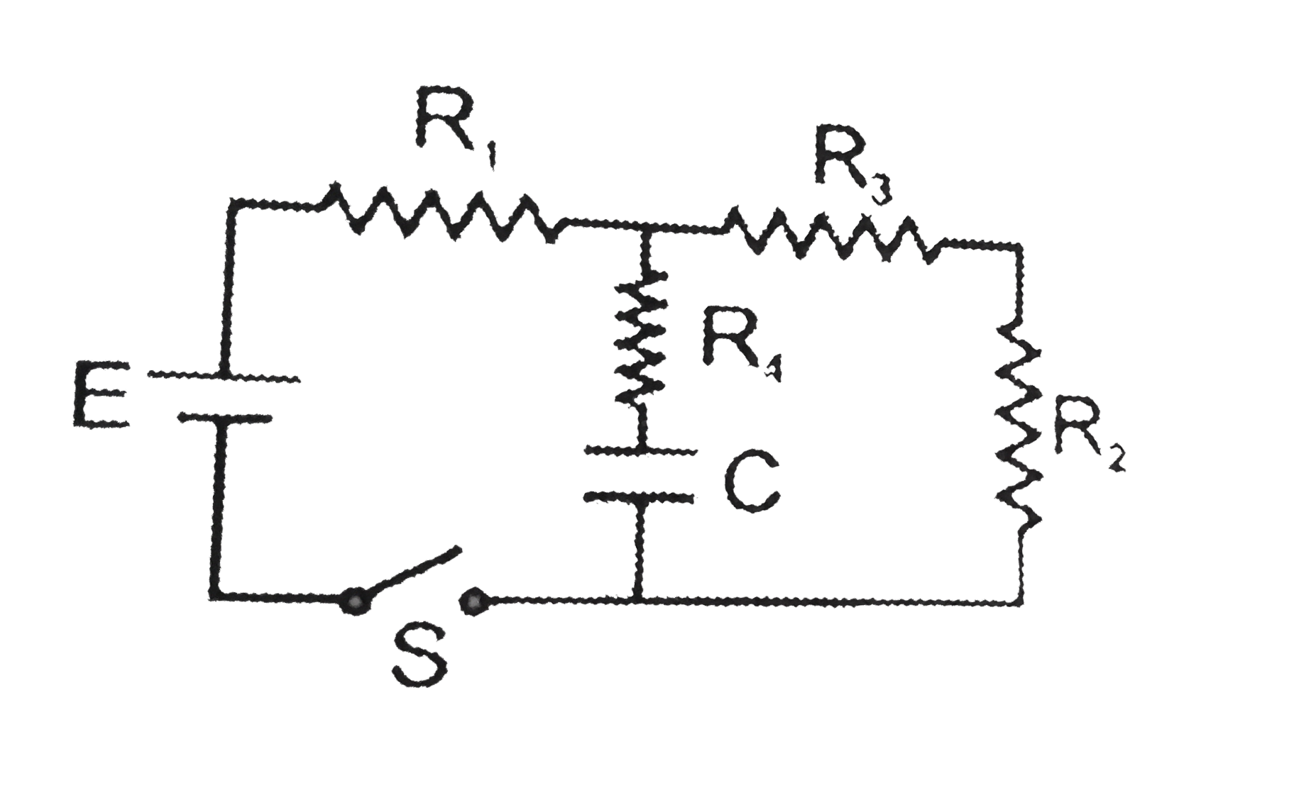
In the circuit shown in the figure, switch S is closed at time t=0. Select the correct statements.

View SolutionIn the circuit shown in the figure, switch S is closed at time t=0. Select the correct statements.

View SolutionThe circuit consists of two resistors (of resistance R1=20Ω and R2=10Ω), a capacitor (of capacitance C=10μF) and two ideal cells. In the circuit shown the capacitor is in steady state and the switch S is open

the circuit is in steady state with switch S closed. Now the switch S is opened. Just after the switch S is opened. the current through resistance R1 is
View SolutionIn the circuit shown in figure switch S is closed at time t=0
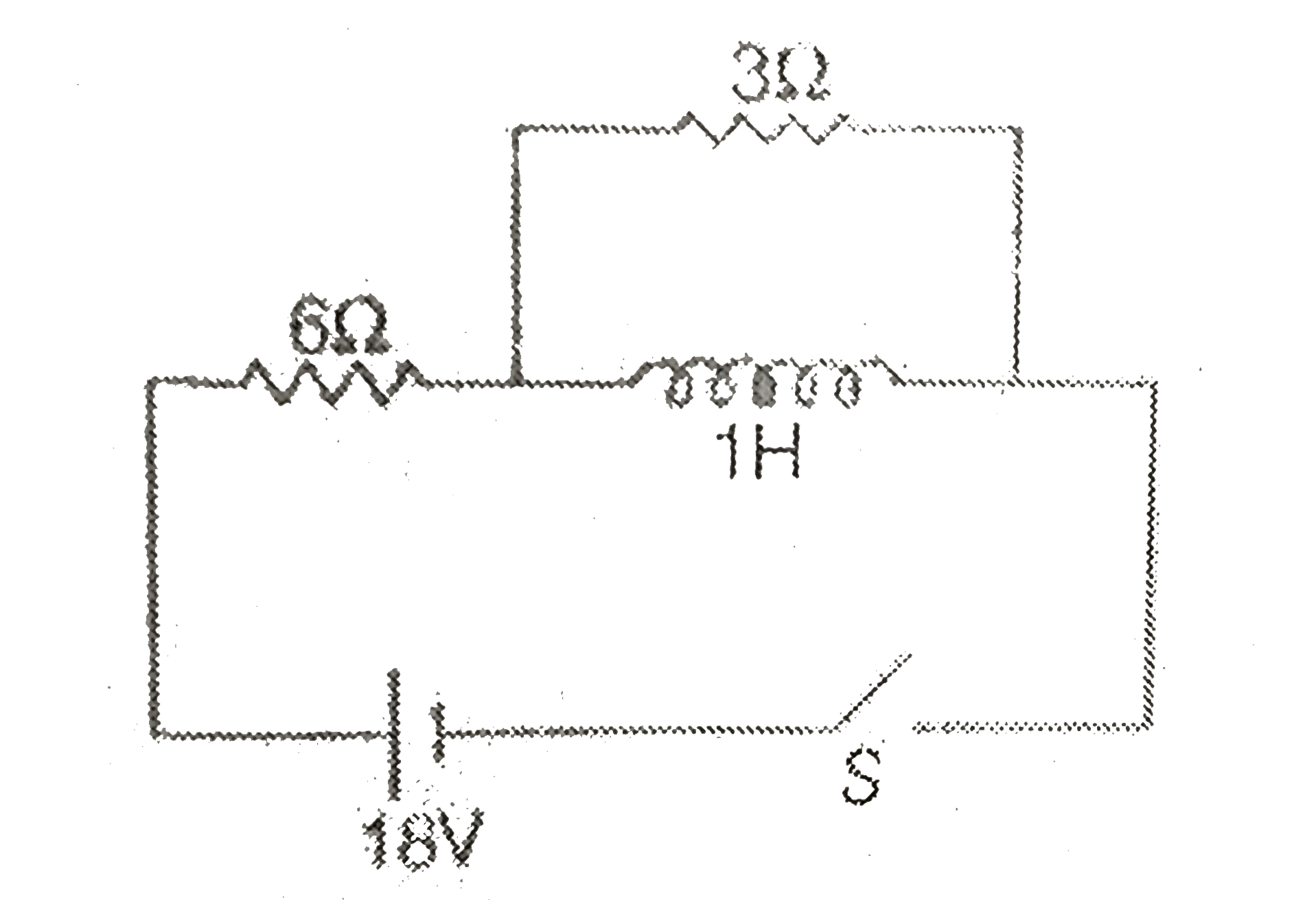
Current I from the battery at time t is given by
View SolutionThe circuit consists of two resistors (of resistance R1=20Ω and R2=10Ω), a capacitor (of capacitance C=10μF) and two ideal cells. In the circuit shown the capacitor is in steady state and the switch S is open

the circuit is in steady state with switch S closed. Now the switch S is opened. Just after the switch S is opened. the current through resistance R1 is
View Solution


