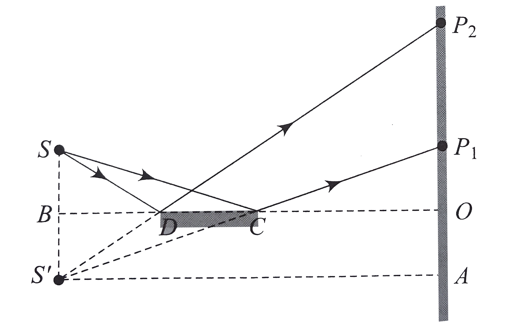
The arrangement for a mirror experiment is shown in figure. S is a point source of frequency 6×10¹⁴Hz. D and C represent the two ends of a mirror placed horizontally and LOM represents the screen.

Calculate the number of fringes
10
20
30
40
The correct Answer is:d
Fringes will be observed in the region between P1 and P2 becasue the reflected rays lie only in this region
From similar triangles BDS' and SP2A,
AP2BS'=AS'BD
∴AP2=(AS')(BS')BD
=(190+5+5)(0.1)5=4 cm
Similarly, in triangle BCS' and S'P1A,
AP1BS'=AS'BD
∴(AS)(BS)BC=(190+5+5)(0.1)10=2 cm
∴P1P2=AP2−AP1=2 cm
Wavelength of the light,
λ=cf=3×1086×1014=5×10⁻⁷ m
Fringe width, β=λDd
Here,D=S'A=190+5+5=200cm=2.0m,d=SS'=2mm
=2×10⁻³m.
∴β=(5×10⁻⁷)(2.0)2×10−3=5×10⁻⁴m
=0.05cm
Therefore, number of fringes =P1P2β=40

Topper's Solved these Questions
- BOOK - CENGAGE PHYSICSCHAPTER - WAVE OPTICSEXERCISE - Integer3videos
WAVE OPTICS
- BOOK - CENGAGE PHYSICSCHAPTER - WAVE OPTICSEXERCISE - Archives4videos
WAVE OPTICS
- BOOK - CENGAGE PHYSICSCHAPTER - WAVE OPTICSEXERCISE - Assertion- Reasoning13videos
WAVE OPTICS
- BOOK - CENGAGE PHYSICSCHAPTER - THERMODYNAMICSEXERCISE - QUESTION BANK34videos
THERMODYNAMICS
- BOOK - CENGAGE PHYSICSCHAPTER - WAVESEXERCISE - QUESTION BANK38videos
WAVES
Similar Questions
A monochromatic light source of frequency 6×10¹⁴Hz is emitting energy at the rate 2×10⁻³J/s. Calculate the number of photons emitted per seconds by source.
View SolutionIn Young's double slit experiment , the light has a frequency of 6×10¹⁴Hz and the distance between the centres of adjacent fringes is 0.75mm. If the screen is 1.5m away, what is the distance between the slits ?
View Solution
Knowledge Check
- Question 1 - Select One
The arrangement for a mirror experiment is shown in figure. S is a point source of frequency 6×10¹⁴Hz. D and C represent the two ends of a mirror placed horizontally and LOM represents the screen.

Find the fringe width of the fringe pattern ?A0.05cmB0.25cmC0.01cmD0.1cm - Question 2 - Select One
The arrangement for a mirror experiment is shown in figure. S is a point source of frequency 6×10¹⁴Hz. D and C represent the two ends of a mirror placed horizontally and LOM represents the screen.

Determine the width of the region where the fringes will be visibleA4cmB6cmC2cmD3cm - Question 3 - Select One
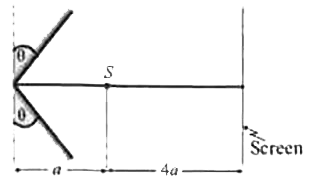
There are two plane mirrors. They are mutually inclined as shown in figure. S is a source of monochromatic light of wavelength λ. The reflected beam interfere and fringe pattern is obtained on the screen. If θ is small, the fringe width will be :
 Aλ/θB3λ/2θC2λ/3θDnone of these
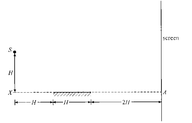
A point source has been placed as shown in the figure-. What is the length on the screen that will receive reflected light from the mirror ?
 View Solution
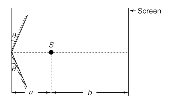
Two plane mirrors, a source S of light, emitting wavelengths ofλ1=4000∘A andλ2=5600∘Aand a screen are arranged as shown in figure. The angle θ shown is 0.05 radian and distance a and b are 1 cm and 38 cm respectively.
(a) Find the fringe width of interference pattern formed on screen by the blue light.
(b) Calculate the distance of first black line from central bright fringe.
(c) Find the distance between two black lines which are nearest to the central bright fringe.
 View Solution
_S01_028_Q01.png)
In the figure shown S is a point monochromatic light source of frequency 6×10¹⁴Hz.M is a concave mirror of radius of curvature 20 cm and L is a thin converging lens of focal length 3.75 cm AB is the principal axis of M and L.
Light reflected from the mirror and refracted from the lens in succession reaches the screen. An interference pattern is obtained on the screen by this arrangement.
Q. Distance between two coherent sources whichmakes interference pattern on the screen isView Solution_S01_029_Q01.png)
In the figure shown S is a point monochromatic light source of frequency 6×10¹⁴Hz.M is a concave mirror of radius of curvature 20 cm and L is a thin converging lens of focal length 3.75 cm AB is the principal axis of M and L.
Light reflected from the mirror and refracted from the lens in succession reaches the screen. An interference pattern is obtained on the screen by this arrangement.
Q. Fringe width isView Solution_S01_030_Q01.png)
In the figure shown S is a point monochromatic light source of frequency 6×10¹⁴Hz.M is a concave mirror of radius of curvature 20 cm and L is a thin converging lens of focal length 3.75 cm AB is the principal axis of M and L.
Light reflected from the mirror and refracted from the lens in succession reaches the screen. An interference pattern is obtained on the screen by this arrangement.
Q. If the lens is replaced by another converging lens of focal length 103cm and the lens is shifted towards right by 2.5 cm thenView Solution

