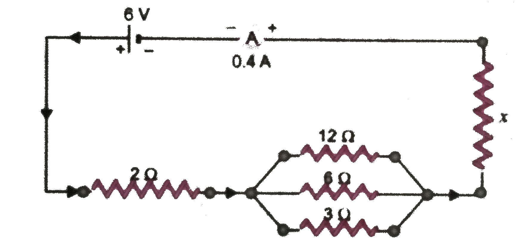
Carefully study the circuit diagram shown and calculate the value of x.
 .
.
A
14.3 ohm
B
11.3 ohm
C
12 ohm
D
23.4 ohm
Video Solution
Text Solution
The correct Answer is:B
The resistances 12Ω,6Ωand3Ω are in parallel. If R1 is their resultant resistance, then
1R1=112+16+13=2+4+824=1424=712 or R1=127Ω
Since 2Ω,R1andx are in series,
total resistance in the circuit, R=2+R1+x=2+127+x=267+x
From Ohm's law, I=VR or 0.4=626/(7)+x
or 267+x=60.4=15 or x=15−267=797Ω=11.3Ω.
|
Updated on:21/07/2023
Topper's Solved these Questions
- BOOK - PRADEEPCHAPTER - ELECTRICITYEXERCISE - (Exemplar)Multiple Choice18videos
ELECTRICITY
- BOOK - PRADEEPCHAPTER - ELECTRICITYEXERCISE - (Mock Test)Sec -A21videos
ELECTRICITY
- BOOK - PRADEEPCHAPTER - ELECTRICITYEXERCISE - Value Based Question4videos
ELECTRICITY
- BOOK - PRADEEPCHAPTER - MAGNETIC EFFECTS OF ELECTRIC CURRENTEXERCISE - Mock Test21videos
MAGNETIC EFFECTS OF ELECTRIC CURRENT
Similar Questions
Knowledge Check
- Question 1 - Select One
In the circuit diagram shown
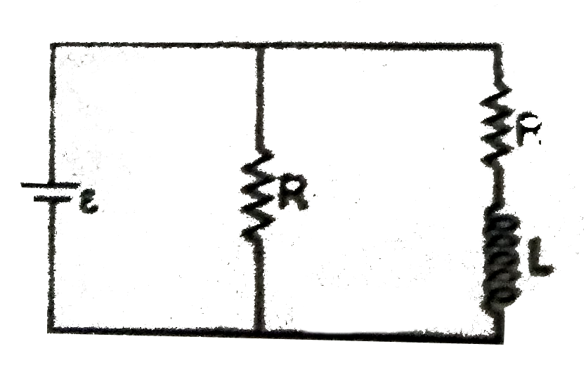 Atime constant is L/RBtime constant is 2L/RCsteady state current in inductor is 2ε/RDsteady state current in inductor is ε/2R
 - Question 2 - Select One or More
In the circuit diagram shown in Fi,
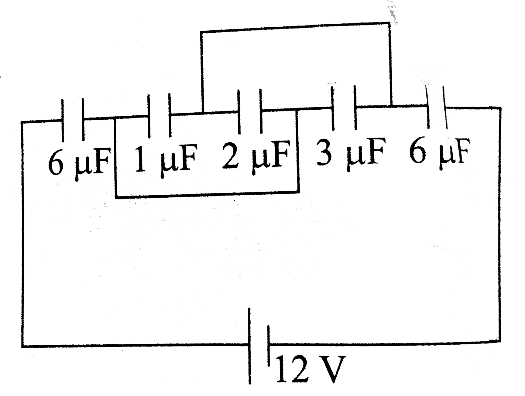 .Athe charge on 2μF capacitor is 8μCBthe charge on each 6μF capacitor is 72μCCthe pottential drop across 1μF capacitor is 4V.Dthe potential drop across 3μF is 4 V
 - Question 3 - Select One
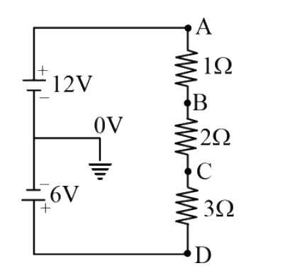
In the circuit diagram shown in figure, the potentials of the points B, C and D are respectively.
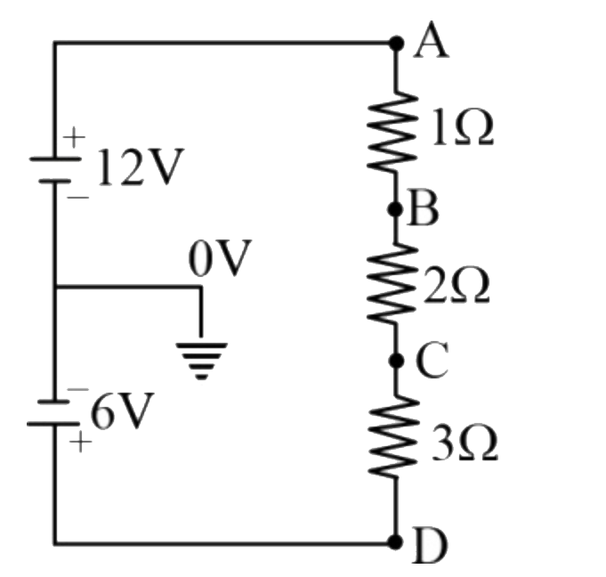 A12V,10V,6VB11V,9V,6VC11V,9V,0VD12V,10V,0V
In the circuit shown in figure, the value of R is
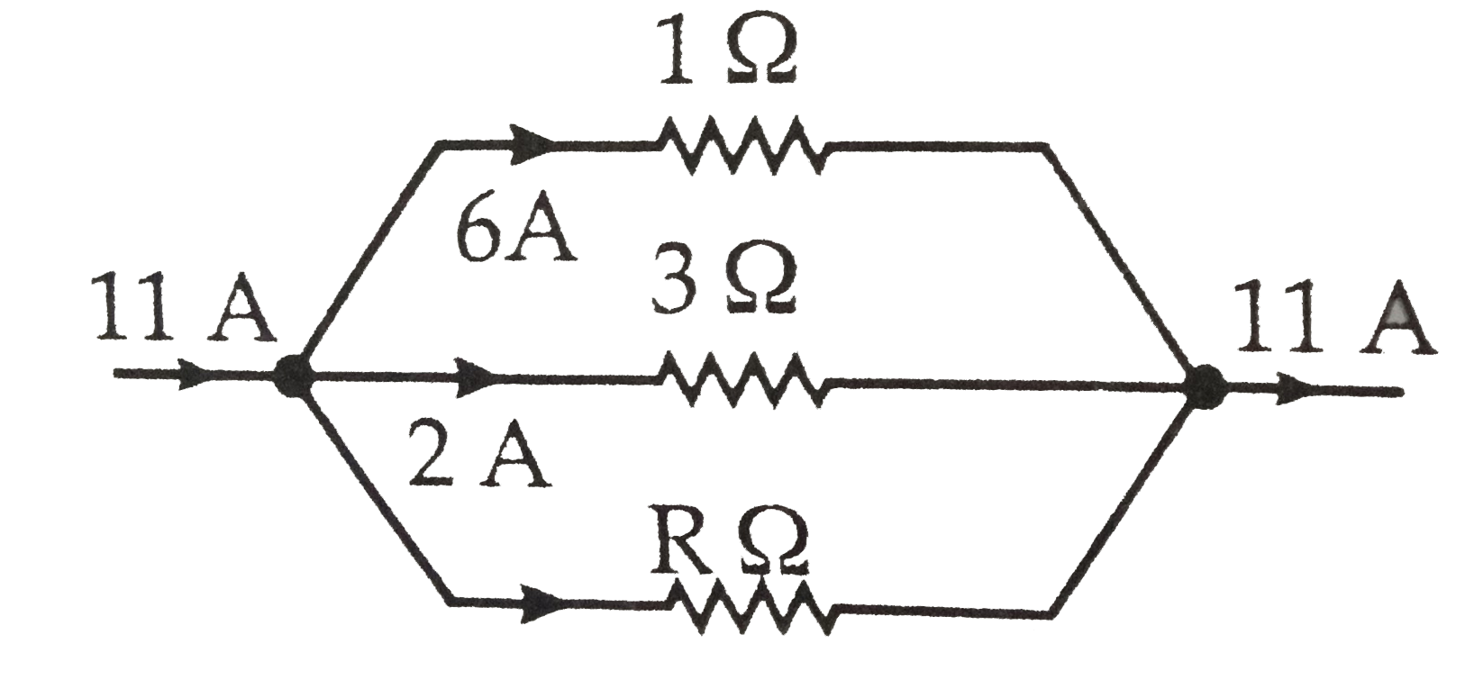 View Solution
(a) With the help of a diagram, derive the formula for the resultant resistance of these resistors connected in series.
(b) For the circuit shown in the diagram given below:
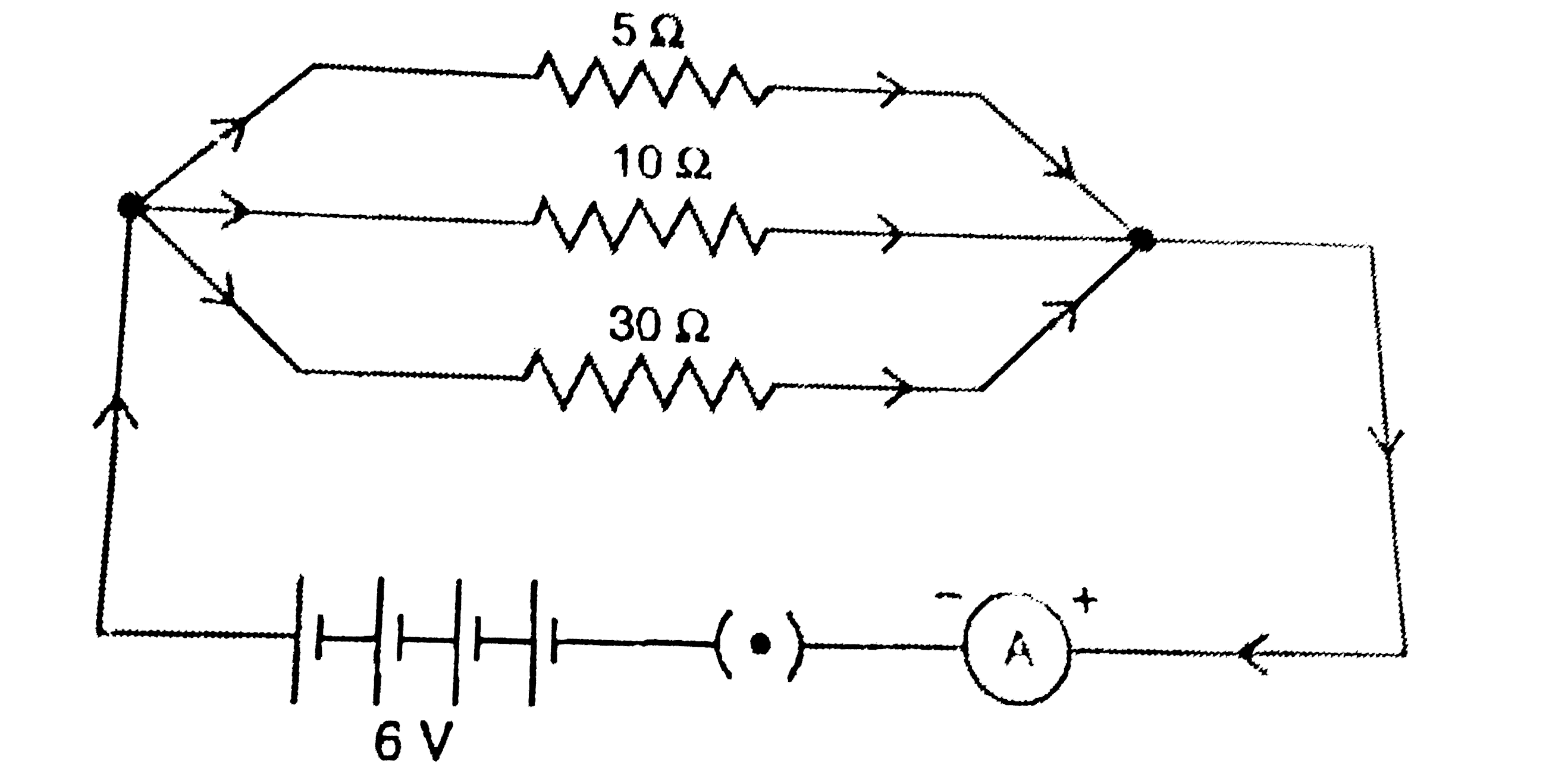
Calculate:
(i) the value of current each resistor.
(ii) the total current in the circuit.
(iii) the total effective resistance of the circuit.View SolutionCalculate I for the given circuit diagram.
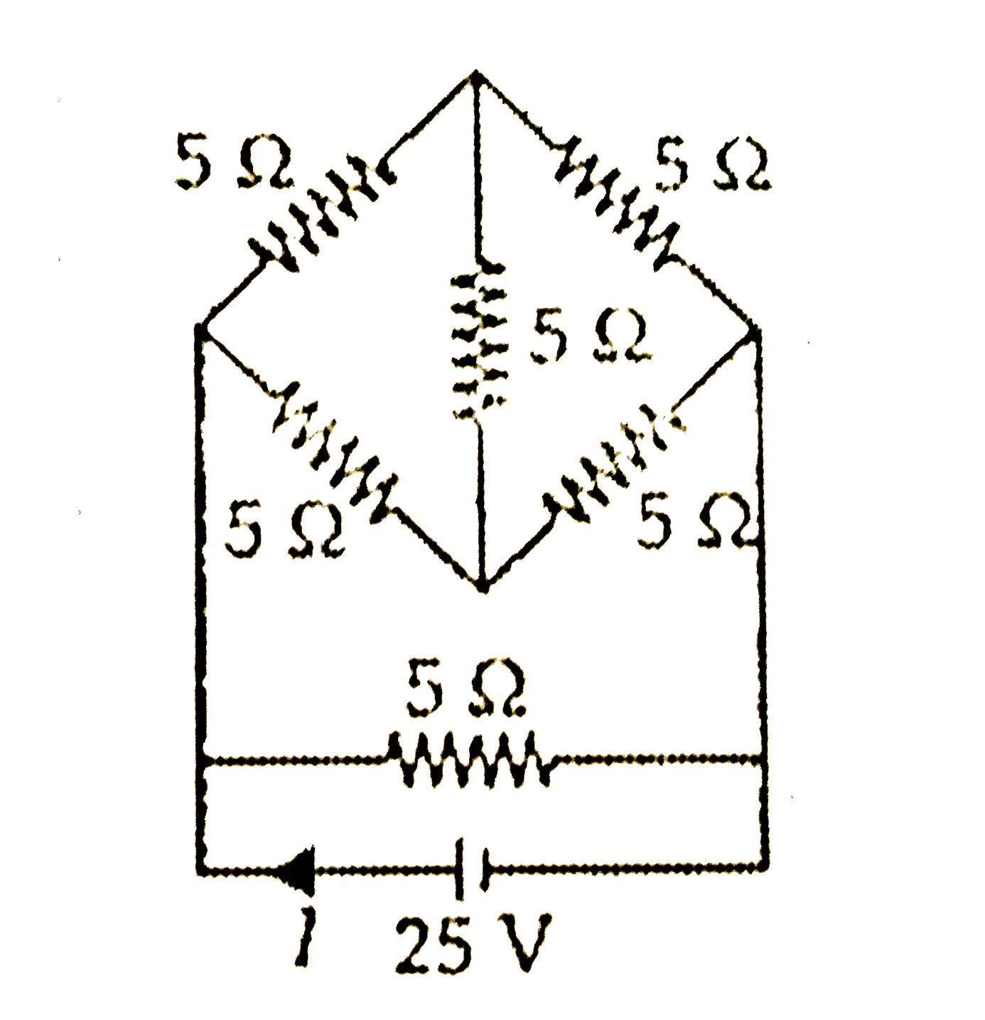 View Solution
In the circuit diagram shown in Figure , the potentials of the points B, C and D are respectively -
 View Solution
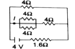
In the circuit shown the value of l in ampere is
 View Solution


