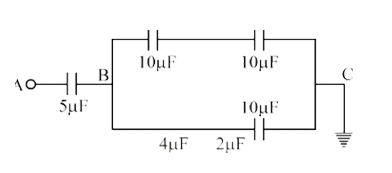
Two condensers C1 and C2 in a circuit are joined as shown in figure. The potential of point A is V1 and that of B is V2 . The potential of point D will be

A
12(V1+V2)
B
C2V1+C1V2C1+C2
C
C1V1+C2V2C1+C2
D
C2V1−C1V2C1+C2
Video Solution
Text Solution
The correct Answer is:C
Charge on C1= charge on C2
⇒C1(VA−VD=C2(VD−VB)
⇒C1(V1−VD)=C2(VD−V2)⇒VD=C1V1+C2V2C1+C2
|
Topper's Solved these Questions
- ELECTRIC POTENTIAL & CAPACITANCEBOOK - A2ZCHAPTER - ELECTRIC POTENTIAL & CAPACITANCEEXERCISE - Capacitor Circuits
52 Videos
- ELECTRIC POTENTIAL & CAPACITANCEBOOK - A2ZCHAPTER - ELECTRIC POTENTIAL & CAPACITANCEEXERCISE - Problems Based On Mixed Concepts
44 Videos
- ELECTRIC POTENTIAL & CAPACITANCEBOOK - A2ZCHAPTER - ELECTRIC POTENTIAL & CAPACITANCEEXERCISE - Capacitor With Dielectric
32 Videos
- ELECTRIC CHARGE, FIELD & FLUXBOOK - A2ZCHAPTER - ELECTRIC CHARGE, FIELD & FLUXEXERCISE - Section D - Chapter End Test
29 Videos
- ELECTROMAGNETIC INDUCTIONBOOK - A2ZCHAPTER - ELECTROMAGNETIC INDUCTIONEXERCISE - Section D - Chapter End Test
30 Videos
Similar Questions
Knowledge Check
Two condensers C1 and C2 in a circuit are jhioned as shown in . The potential fo point A is V1 and that of B is V2 . The potential of point D will be
 A12(V1+V2)BC1V2+C2V1C1+C2CC1V1+C2V2C1+C2DC2V1−C1V2C1+C2
Two capacitors C1 and C2 in a circuite are joined as shown. If VA=V1,VB=V2, the potemntial of point P is
 A12(V1−V2)BC2V1+C1V2C1+C2CC1V1+C2V2C1+C2DC2V1−C1V2C1+C2
Two capacitors C1 and C2 are connected in a circuit as shown in figure. The potential difference (VA−VB) is
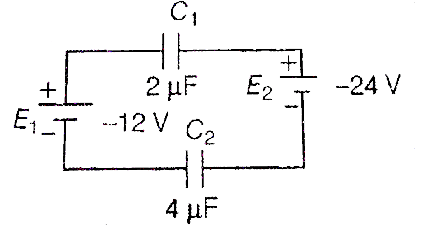 A8VB−8VC12VD12V
In Figure if the potential at Point P is 100V, what is the potential at point Q?
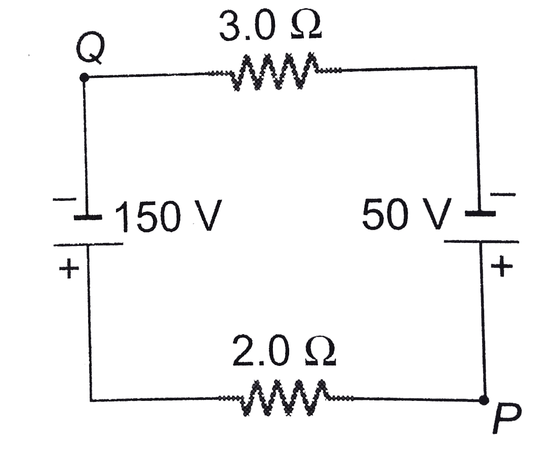
View SolutionFour capacitors C1,C2,C3 and C4 are connected as shown in figure.If potential difference between points A and B is zero, then
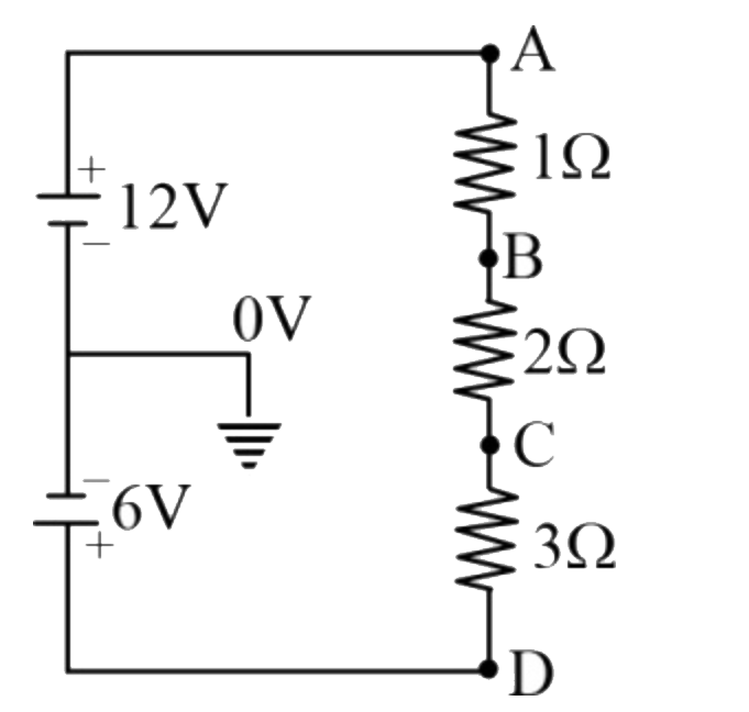
View SolutionIn the circuit diagram shown in figure, the potentials of the points B, C and D are respectively.
View SolutionIn the circuit shown in the figure, if the potential at point A behind to be zero, the potential at point B is :
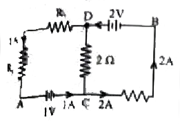
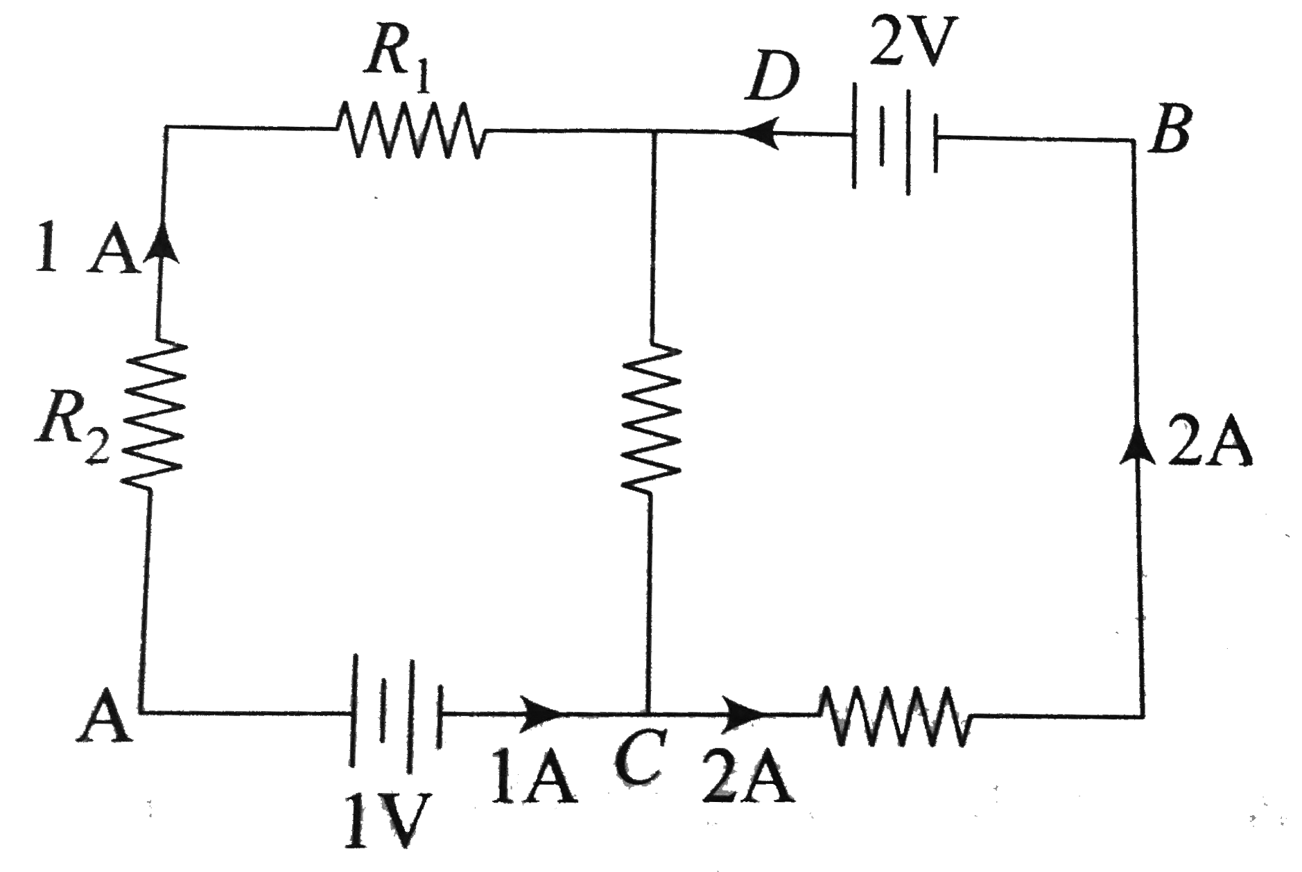
View SolutionIn the circuit shown in the figure, if potentail at point A is taken to be zero, the potential at point B is
View Solution
