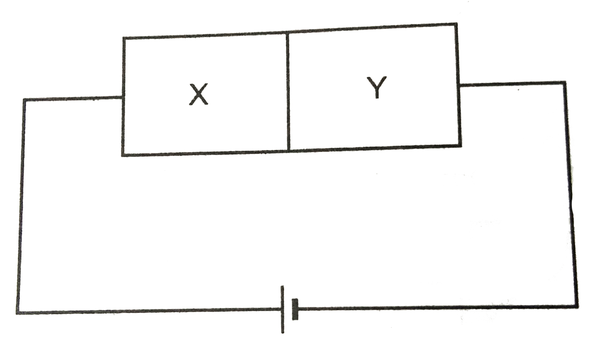
In Fig. the input is across the terminals A and C and the output is across B and D. Then the output is
half wave rectified
full wave rectified
zero
same as the input
The correct Answer is:B
It is a circuit for full wave rectifier.
Topper's Solved these Questions
- ELECTRONIC DEVICESBOOK - PRADEEPCHAPTER - ELECTRONIC DEVICESEXERCISE - INTEGER TYPE QUESTION
2 Videos
- ELECTRONIC DEVICESBOOK - PRADEEPCHAPTER - ELECTRONIC DEVICESEXERCISE - MULTIPLE CHOICE QUESTIONS
2 Videos
- ELECTRONIC DEVICESBOOK - PRADEEPCHAPTER - ELECTRONIC DEVICESEXERCISE - PROBLEMS FOR PRACTICE
7 Videos
- ELECTROMAGNETIC WAVESBOOK - PRADEEPCHAPTER - ELECTROMAGNETIC WAVESEXERCISE - II Focus multiple choice question
5 Videos
- ELECTROSTATICSBOOK - PRADEEPCHAPTER - ELECTROSTATICSEXERCISE - ASSERTION-REASON TYPE QUESTIONS
2 Videos
Similar Questions
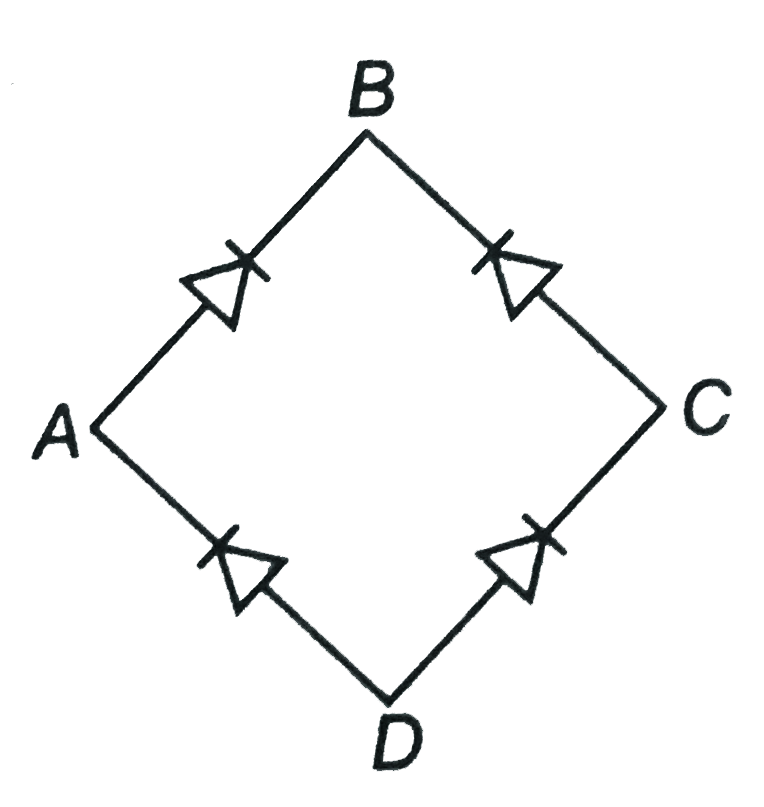
In the figure, the input is across the terminals
A and C and the output is across B and D. Then the output is
(a ) zero
( b) same as the input
( c) full - wave rectified
(d) half - wave rectified .
View SolutionIn the figure, the input is across the terminals
A and C and the output is across B and D. Then the output is

(a ) zero
( b) same as the input
( c) full - wave rectified
(d) half - wave rectified .
View Solution
Knowledge Check
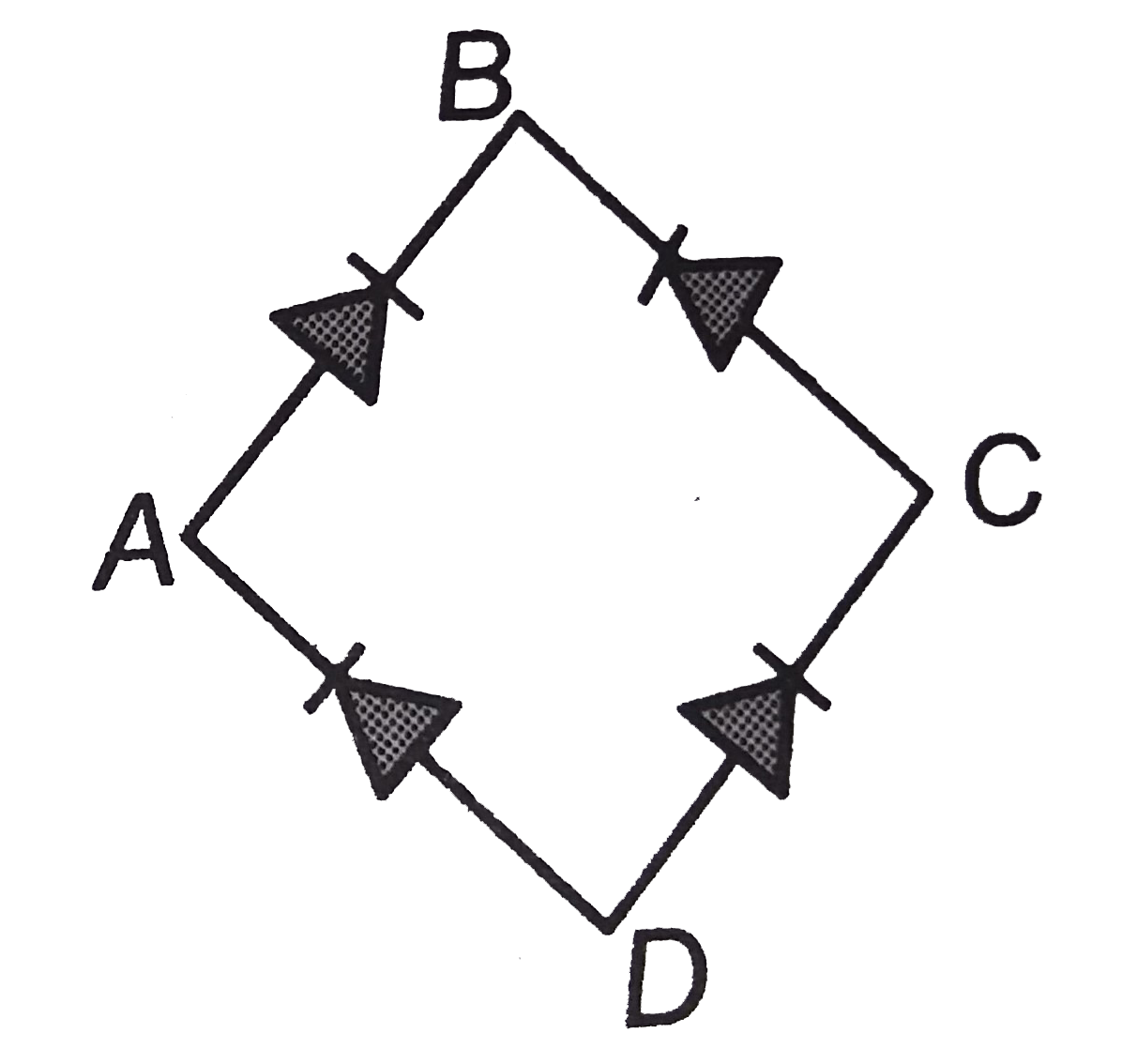
In the diagram, the input is across the terminals A and C and the output is across the terminals B and D, then the outputs is
 AzeroBsame as inputCFull wave rectifierDHalf wave rectifier
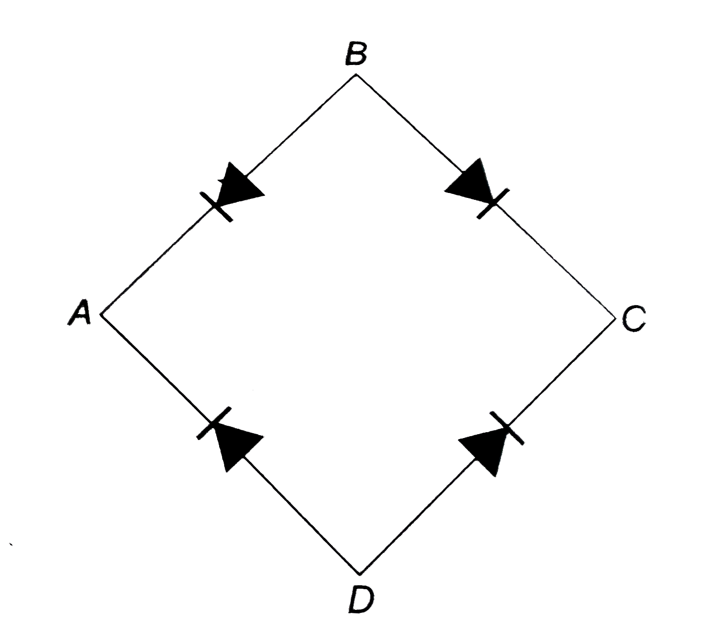
A bridge rectifier is shown in figure. Alternating input is given across A and C. If output is taken across BD, then it is
 AzeroBsame as inputChalf wave rectifiedDfull wave rectified
In AND gate, the output Y is 1 when the inputs A and B are:
AA=1, B=0BA=1, B=1CA=0, B=0DA=0, B=1
If A & B are the input as shown in the figure , then output will be

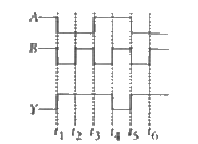
View SolutionThe figure shows the voltage waveforms across two inputs A and B and the output Y of a logic circuit. The logic circuit gate is
View SolutionIn the circuit givne, A, B and C are inputs and Y is the output.

The output of Y is
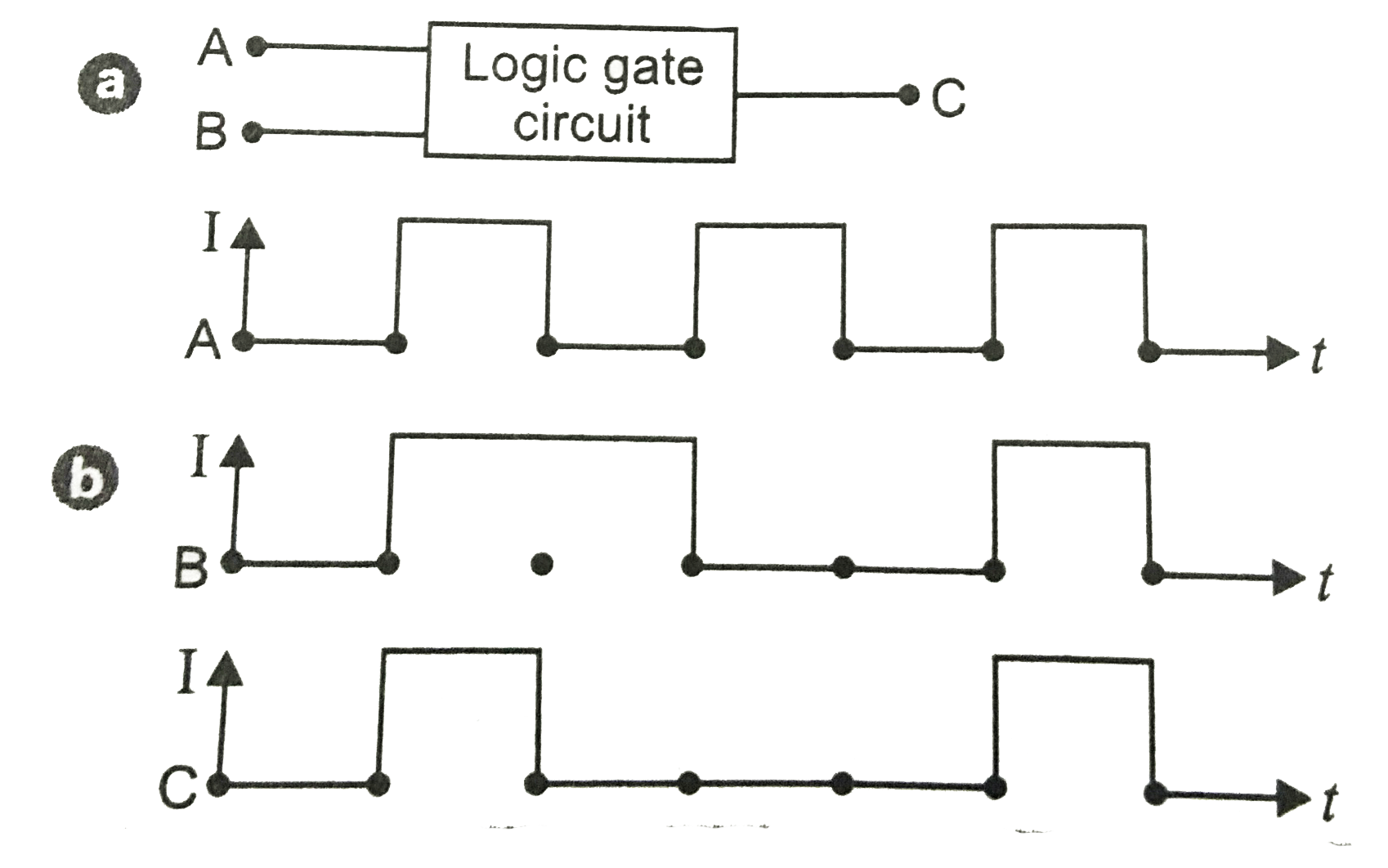
View SolutionThe Fig.shows a logic gate circuit with two inputs A and B and the output C are as shown in Fig.
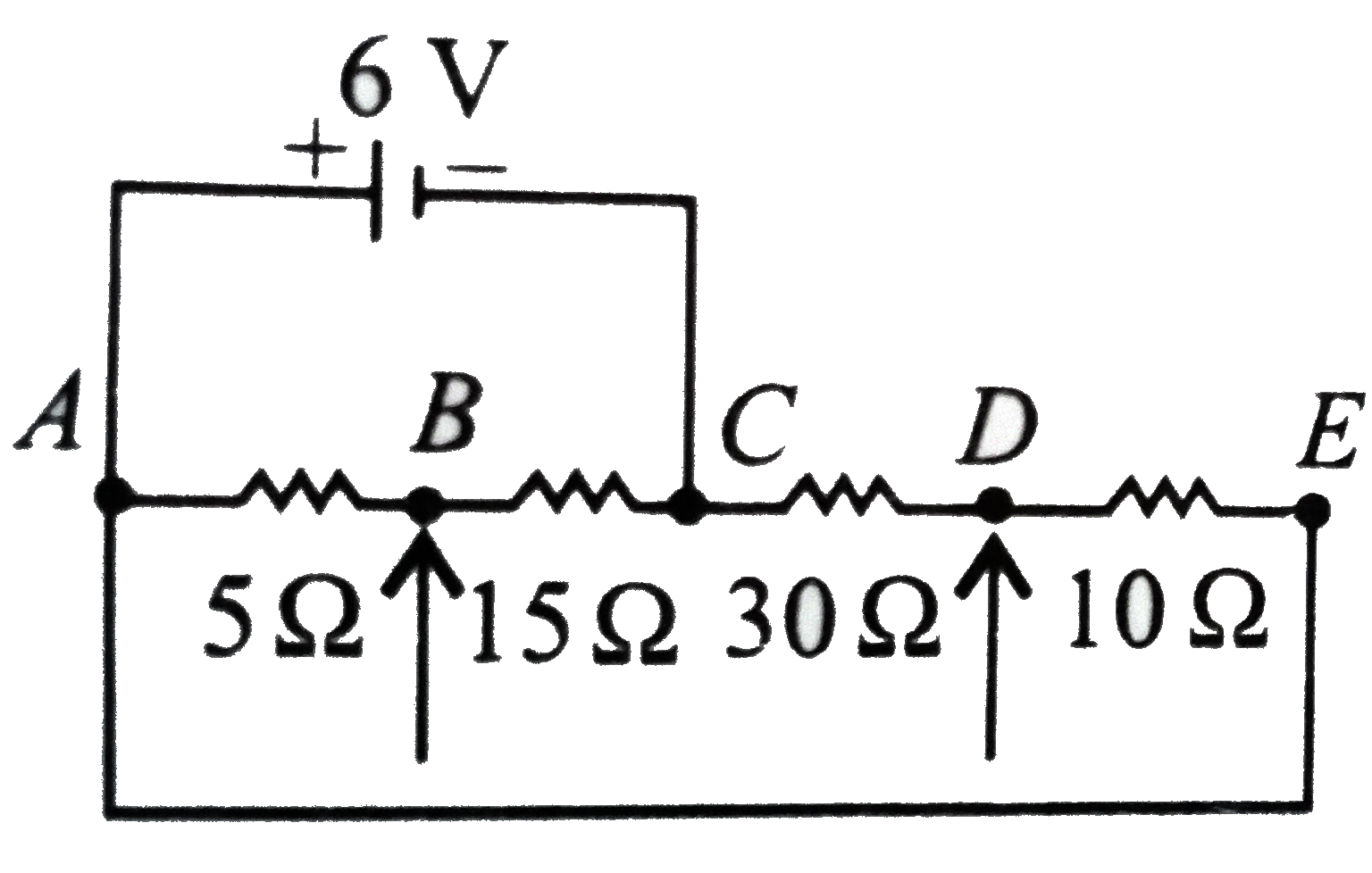
View SolutionFour resistors are connected as shown in the figure. A 6 V battery of negligible resistance is connected across terminal battery of negligible resistance A and C. The potential difference across terminal B and D will be
View Solution
