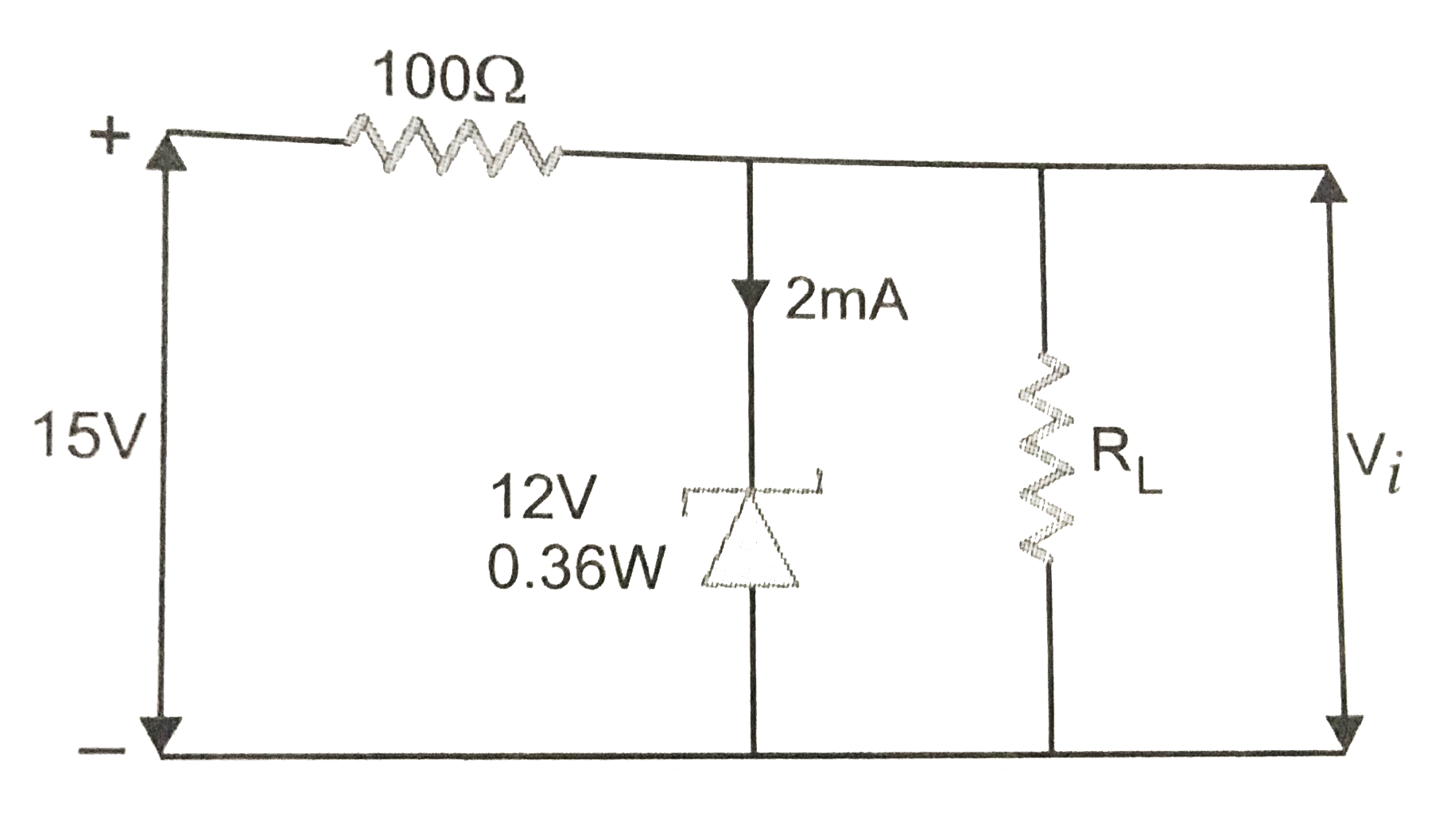
In the circuit Fig., what is the range over which the load resistance can be varied?
298.6Ω≤RL<∞
303.7mega≤RL<∞ only
408.2mega≤RL<∞ only
428.6mega≤RL<∞ only
The correct Answer is:D
Pot. Diff. across 100Ω=15−12=3V
current through 100Ω
I=3V100Ω=0.03A=30mA
Current through RL=30−2=28mA
Pot. Diff. across ∴RL=12V
RL=12V28×10−3Ω=428.6Ω If RL=∞, then voltage across zener diode will be more than 12 V and it will not work properly.
Topper's Solved these Questions
- BOOK - PRADEEPCHAPTER - ELECTRONIC DEVICESEXERCISE - LONG QUESTION ANSWER2videos
ELECTRONIC DEVICES
- BOOK - PRADEEPCHAPTER - ELECTRONIC DEVICESEXERCISE - PROBLEMS FOR PRACTICE7videos
ELECTRONIC DEVICES
- BOOK - PRADEEPCHAPTER - ELECTRONIC DEVICESEXERCISE - HIGHER ORDER THINKING SKILLS1videos
ELECTRONIC DEVICES
- BOOK - PRADEEPCHAPTER - ELECTROMAGNETIC WAVESEXERCISE - II Focus multiple choice question5videos
ELECTROMAGNETIC WAVES
- BOOK - PRADEEPCHAPTER - ELECTROSTATICSEXERCISE - ASSERTION-REASON TYPE QUESTIONS2videos
ELECTROSTATICS
Similar Questions
In the circuit shown in the figure , the resistance marked R can be varied by using a Rheostat. The power across the 5 Omega resistor will be maximum if the Rhoestat has resistance equal to
_PHY_E01_015_Q01.png) View Solution
View SolutionAn alternating-current emf device in a certain circuit has a smaller resistance than that of the resistive load in the circuit , to increase the transfer of energy from the device to the load , a transformer will be connected between the two . (a) Should Ns be greater than or less than Np ? (b) Will that make it a step-up or step-down transformer ?
View Solution
Knowledge Check
- Question 1 - Select One
A circuit is shown in the figure.
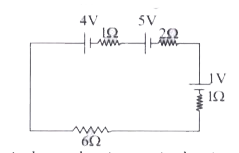
What is the total resistance in the circuit ?A5B6C11D30 - Question 2 - Select One
What is the current through 1Ω resistance? Fig.
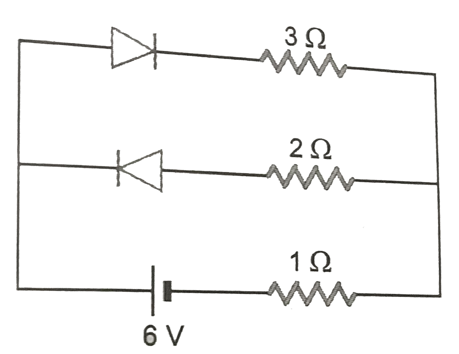 A1.6 AB1.5 AC3.0 AD6.0 A
 - Question 3 - Select One
To decrease the range of an ammeter its resistance need to be incrased an ammeter has resistacne R0 and range / which of the following resistance can be connected in series with it to drecease its range to l/n
AR0nBR0n−1CR0n+1Dnone of these
In the circuit shown in Fig. 27-47, there is a cube of resistances which are all having the same resistance of R. Find the equivalent resistance of the network between diagonally opposite points as shown in the figure.
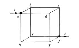 View Solution
Determine the load resistance for which the power delivered to the circuit is a maximum. Graph the dependence of the power on the load resistance.
View SolutionIn the circuit shows in Fig. 6.42, resistors X and Y, each with resistance R, are connected to a 6V battery of negligible internal resistance. A voltmetre, also of resistance R, is connected across Y.
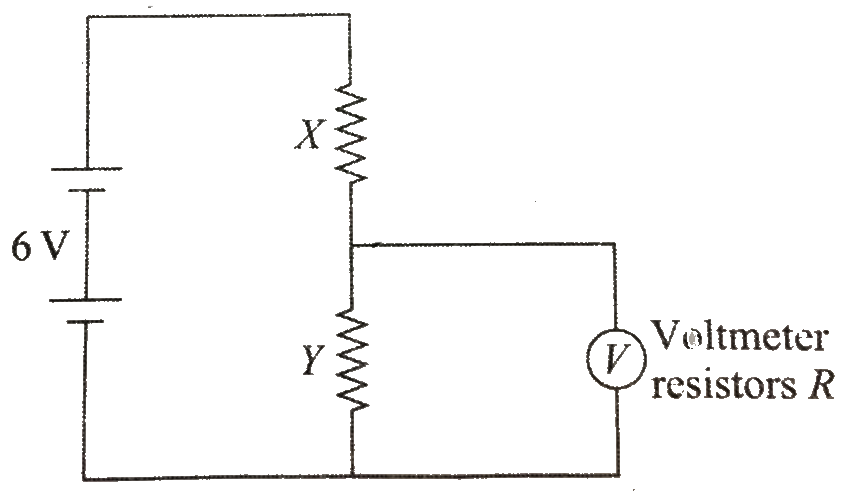
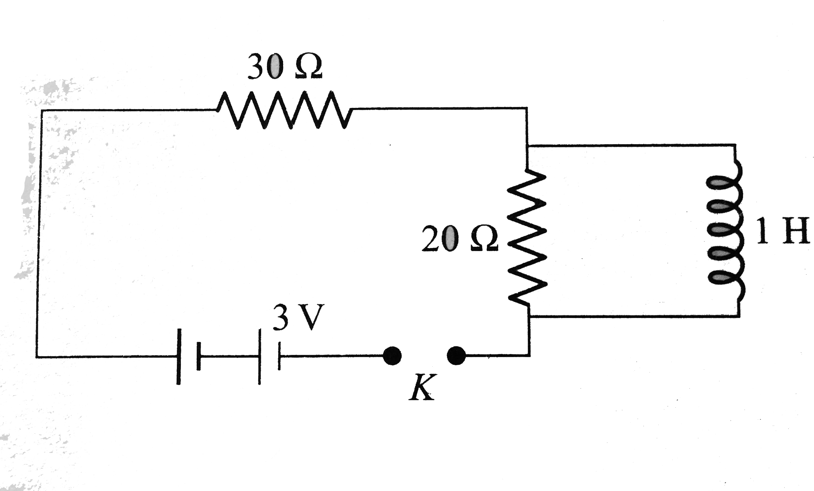
What is the reading of the voltmeter?View SolutionIn the circuit Fig the final current through 30Ω resistance when circuit is completed is
 View Solution
A transistor is connected in commono emitter configuration. The collector emitter voltage is 8 V and load resistance of 8000Ω is connected in the collector circuit the voltage drop across the load resistance is 0.5V. If the current gain be 0.96, what is the base current
View Solution

