In the circuit shown in Fig, the enf of each battery is E=12 votl and the capacitances are C1=2.0μF and C2=3.0μF. Find the charges which flow along the paths 1,2,3 when K is pressed.
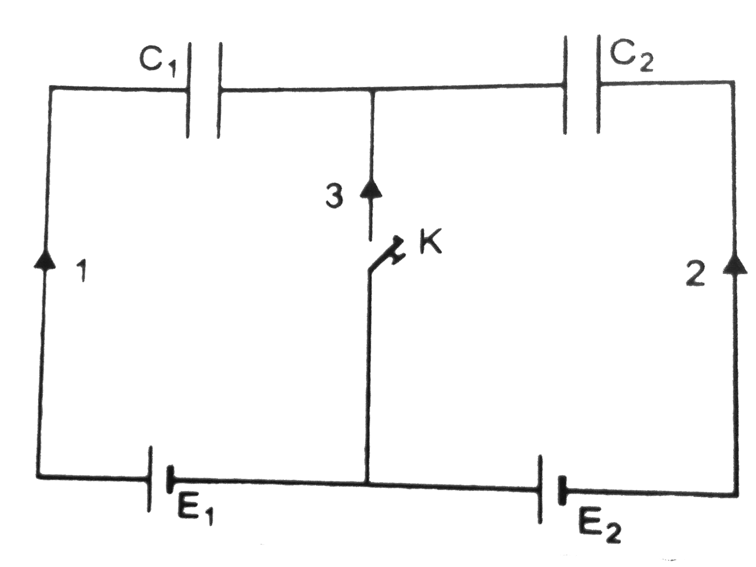
The correct Answer is:24μC;−36μC;12μC
NA
Topper's Solved these Questions
- ELECTROSTATICSBOOK - PRADEEPCHAPTER - ELECTROSTATICSEXERCISE - MULTIPLE CHOICE QUESTIONS
5 Videos
- ELECTROSTATICSBOOK - PRADEEPCHAPTER - ELECTROSTATICSEXERCISE - COMPREHENSION
2 Videos
- ELECTROSTATICSBOOK - PRADEEPCHAPTER - ELECTROSTATICSEXERCISE - FILL IN THE BLANKS
8 Videos
- ELECTRONIC DEVICESBOOK - PRADEEPCHAPTER - ELECTRONIC DEVICESEXERCISE - Fill in the Blanks
1 Videos
- MAGNETIC EFFECT OF CURRENT AND MAGNETISMBOOK - PRADEEPCHAPTER - MAGNETIC EFFECT OF CURRENT AND MAGNETISMEXERCISE - Competition Focus (Multiple Choice Questions)
2 Videos
Similar Questions
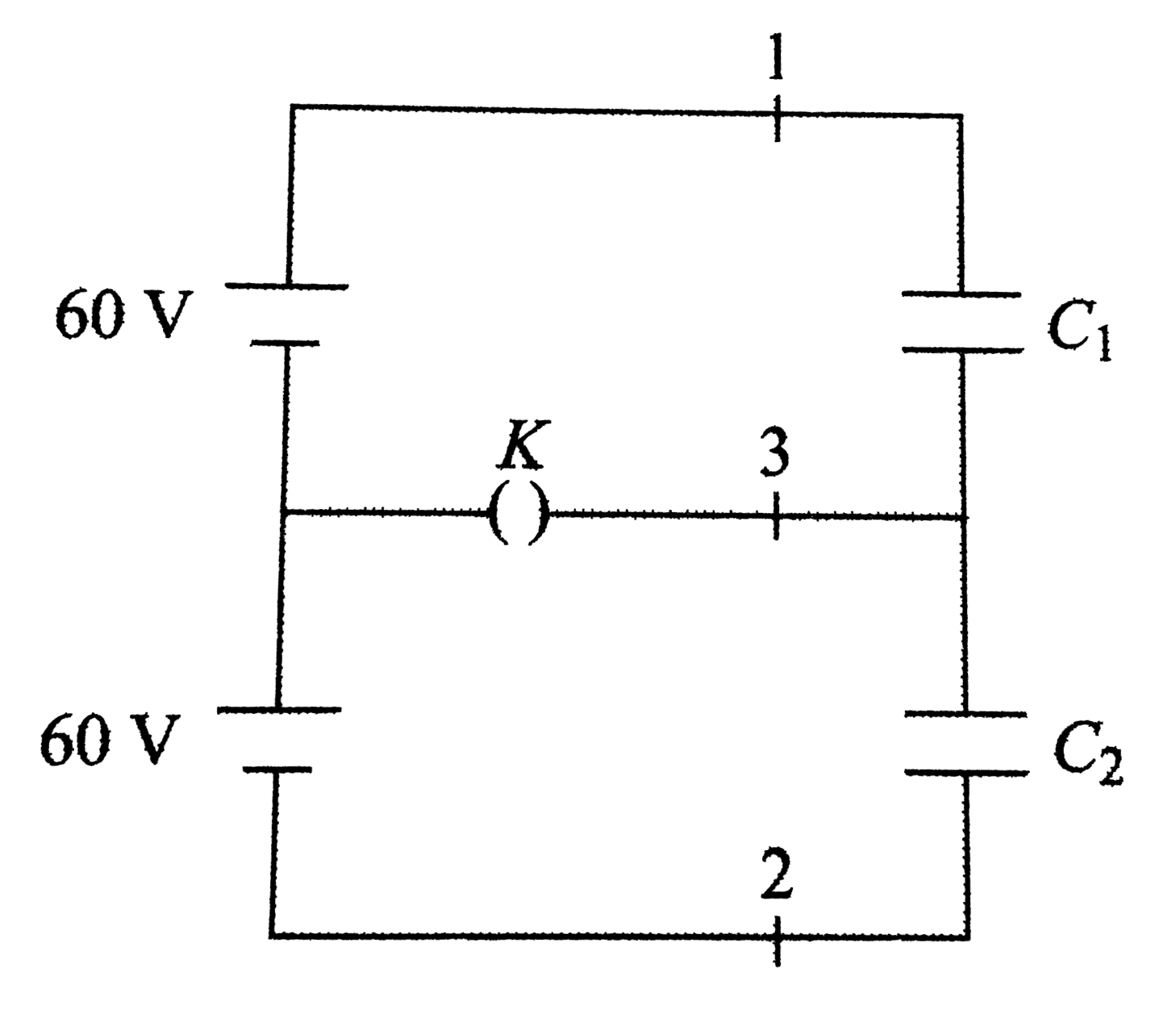
In the circuit shown , the emf of each battery is 60V and C1=2μF and C2=3μF. Find the charges that will flow through the sections 1,2 and 3 after the Key is closed.
 .
.
View SolutionIn the circuit shown , the emf of each battery is 60V and C1=2μF and C2=3μF. Find the charges that will flow through the sections 1,2 and 3 after the Key is closed.
 .
.
View Solution
Knowledge Check
Find the charges on the three capacitors connected to a battery as shown in figure. Take C1=2.0μF,C2,=4.0μF,C3=6.0μF and V =10 volt
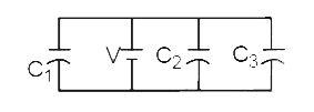 A20μC,40μC,60μCB40μC,20μC,60μCC60μC,40μC,20μCD40μC,60μC,20μC
In the circuit shown below C1=10μF, C2=C3=20μF, and C4=40μ F. if the charge on C1 is 20μC then potential difference between X and Y is
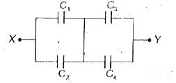 A2 VB3 VC6 VD3.5 V
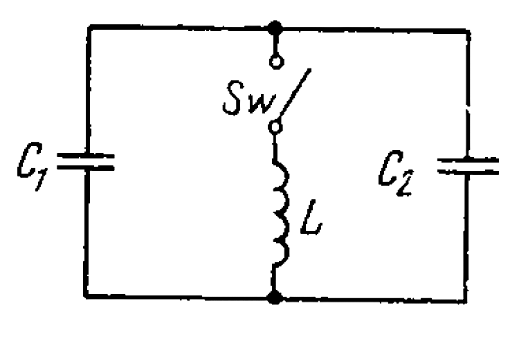
In an oscillating circuit shown in figure, the coil inductance is equal to L=2.5μF. The capacitor have capacitances C1=2.0μF and C2=3.0μF. The capacitors were charged to a voltage V=180V, and then the switch Swwas closed. Find :
(a) the natural oscillation frequency,
(b) the peak value of the current flowing through the coil.
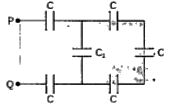
View SolutionFind the equivalent capacitance between P and Q if C1=6μFandC=9μF
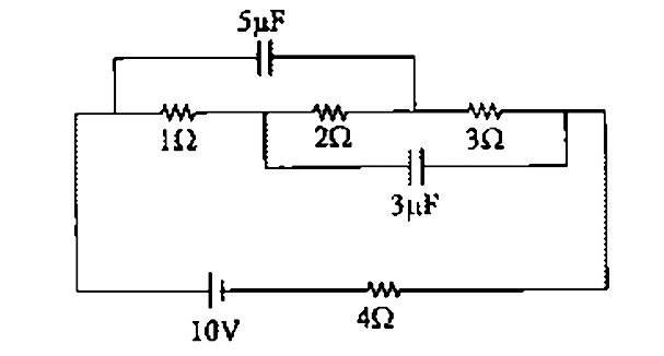
View SolutionIn the circuit shown in figure-3.395, find the charges on capacitors of capacitances 5μFand3μF, in steady state.
View SolutionAn infinite ladder network consisting of all equal resistances, r=102.732Ω is placed side by side to a capacitor system as shown in fig. Initially, all the switches are kept open and all the three capacitors are given equal charges of 30μCeach. The capacitances are C1=3μF,C2=6μFandC3=6μF. Polarity of charges on the capacitor plates is shown in the fig. Now all the three switches are closed simultaneously.
(a) find the magnitude of rate of change of charge on the plates of the capacitors immediately after the switches are closed.
(b) Calculate heat generated in the circuit by the time steady sate condition is established.

View SolutionIn the circuit shown below C1=10μF, C2=C3=20μF, and C4=40μ F. if the charge on C1 is 20μC then potential difference between X and Y is

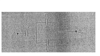
View SolutionIn the arrangement C1=10μ,FC2=10μF and C3=20μF . What is the equivalent capacitance ( in μF ) between points A and B ?
View Solution
