In the circuit shown below C1=10μF, C2=C3=20μF, and C4=40μ F. if the charge on C1 is 20μC then potential difference between X and Y is
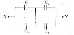
2 V
3 V
6 V
3.5 V
The correct Answer is:B
Step by step video & image solution for In the circuit shown below C_(1) = 10 mu"F, " C_(2) = C_(3) = 20 muF, and C_(4) = 40 mu F. if the charge on C_(1) is 20 muC then potential difference between X and Y is by Physics experts to help you in doubts & scoring excellent marks in Class 12 exams.
Updated on:21/07/2023Topper's Solved these Questions
- ELECTROSTATIC POTENTIAL AND CAPACITANCE BOOK - AAKASH INSTITUTE ENGLISHCHAPTER - ELECTROSTATIC POTENTIAL AND CAPACITANCE EXERCISE - ASSIGNMENT SECTION - B
38 Videos
- ELECTROSTATIC POTENTIAL AND CAPACITANCE BOOK - AAKASH INSTITUTE ENGLISHCHAPTER - ELECTROSTATIC POTENTIAL AND CAPACITANCE EXERCISE - ASSIGNMENT SECTION - C
53 Videos
- ELECTROSTATIC POTENTIAL AND CAPACITANCE BOOK - AAKASH INSTITUTE ENGLISHCHAPTER - ELECTROSTATIC POTENTIAL AND CAPACITANCE EXERCISE - EXERCISE
20 Videos
- ELECTROMAGNETIC WAVESBOOK - AAKASH INSTITUTE ENGLISHCHAPTER - ELECTROMAGNETIC WAVESEXERCISE - ASSIGNMENT SECTION - D Assertion-Reason Type Questions
25 Videos
- GRAVITATION BOOK - AAKASH INSTITUTE ENGLISHCHAPTER - GRAVITATION EXERCISE - ASSIGNMENT SECTION - D (ASSERTION-REASON TYPE QUESTIONS)
15 Videos
Similar Questions
In the circuit below C1=20μF , C2=40μ F and C3=50μ F . If no capacitor can sustain more than 50 V, then maximum potential difference between X and y is

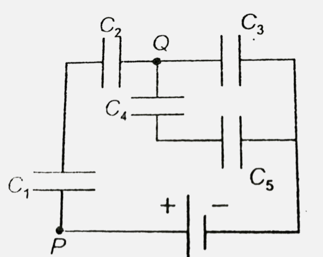
View SolutionIn the circuit shown C1=15μF,C2==30μF,C3=30μF,C4=30μF and C5=60μF. At steady state, the potential difference between points P and Q is 50 V. Calculate the potential difference across capacitor with capacitance C5
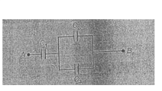
View SolutionIn the arrangement C1=10μ,FC2=10μF and C3=20μF . What is the equivalent capacitance ( in μF ) between points A and B ?
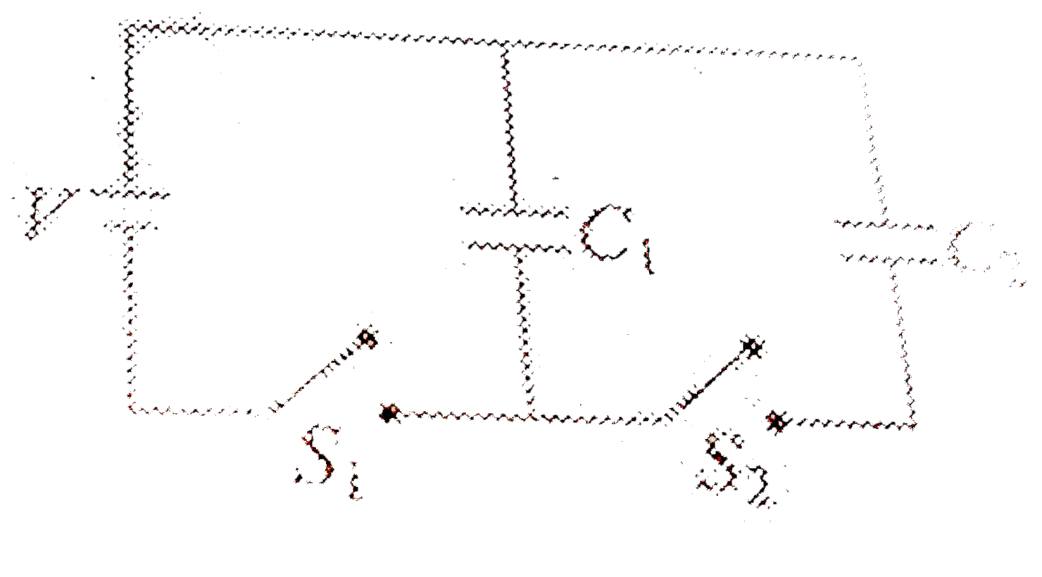
View SolutionConsider the circuit shown where C1=6μF,C2=3μF and V=20V. Capacitor C1 is first charged by closing the switch S1. Switch S1 is then opened, and the charged capacitor is connected to the uncharged capacitor C2 by closing S2.
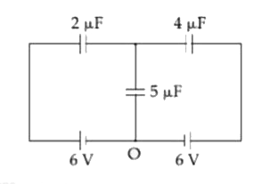
View SolutionIn the circuit shown , charge on the 5μF capacitor is :
View SolutionCondering the situation of the previous question, two experiments wer conducted whose details are as given :
Experiment 1 :Q=10μC
q=50μC
R=15cm
r=10cm
Experiment 2 :Q=20μC
q=60μC
R=15cm
r=10cm
In which case the potential difference between the shells is more ?
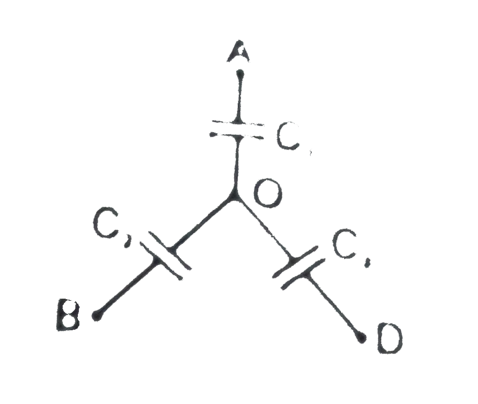
View SolutionThree uncharged capacitors of capacitance C1=1μF,C2=2μF and C3=3μF are connected as shown in the figure. The potential of point A, B and D are 10 volt, 25 volt and 20 volt respectively. Determine the potential at point O.
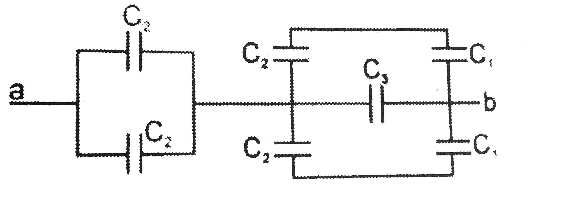
View SolutionA combination arrangement of the capacitors is shown in the figure
(i) C1=3μF,C2=6μF and C3=2μF then equivalent capacitance between 'a' and 'b' is :
View SolutionIn the circuit shown in figure. Charge stored in 6μF capacitor will be (C=6μF)

View SolutionFour point charges qA=2μC,qB=−5μC,qC=2μCandqD=−5μC are located at the corners of a square ABCD of side 10 cm. What is the force on a charge of 1μC placed at the center of the square ?
View Solution
