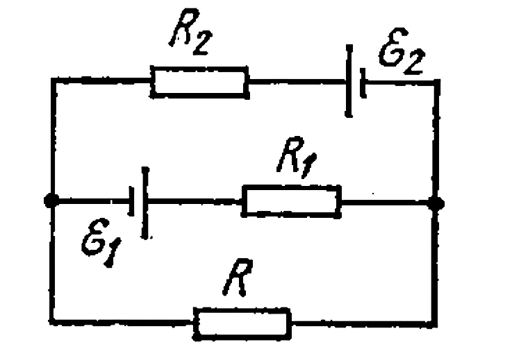
In the circuit shown in Fig, the sources have emf'sξ1=1.5V,ξ2=2.0V,ξ3=2.5V , and the resistances are equal to R1=10Ω,R2=20Ω,R3=30Ω. The internal resistances of the sources are negligible. Find : ltbrtgt (a) the current flowing thorugh teh resistance R1 ,
(b) a potential differences φA−φB between the points A and B between the points A and B.

At first indicate the currents in the branches using charge conservation (which also inclued the point rule).
In the loops 1 BA 61 and B34AB from teh loop rule, −Δφ=0, we get respectively
−ξ2+(i−i1)R2+ξ1−i,Ri=0 ...(1)
iR3+ξ3−(i−i2)R2+ξ2=0 ....(2)
On Solving Eqs. (1) and (2), we obtain
i1=(ξ1−ξ2)R3+R2(ξ1+ξ3)R1R2+R2R3+R3R1=0.06A
Thus φA−φB=ξ2−i2R2=0.9V

Topper's Solved these Questions
- BOOK - IE IRODOV, LA SENA & SS KROTOVCHAPTER - ELECTRODYNAMICSEXERCISE - Constant Magnetic Fiels - Magnetics69videos
ELECTRODYNAMICS
- BOOK - IE IRODOV, LA SENA & SS KROTOVCHAPTER - ELECTRODYNAMICSEXERCISE - Electromagnetic Induction84videos
ELECTRODYNAMICS
- BOOK - IE IRODOV, LA SENA & SS KROTOVCHAPTER - ELECTRODYNAMICSEXERCISE - Electric Capacitance - Energy Of An Electric Field46videos
ELECTRODYNAMICS
- BOOK - IE IRODOV, LA SENA & SS KROTOVCHAPTER - ELECTRICITY AND MAGNETISMEXERCISE - All Questions6videos
ELECTRICITY AND MAGNETISM
- BOOK - IE IRODOV, LA SENA & SS KROTOVCHAPTER - ELECTROMAGNETISMEXERCISE - All Questions24videos
ELECTROMAGNETISM
Similar Questions
In the circuit shown in Fig the sources have emf'sξ1=1.0V and ξ2=2.5V and teh resistances have the values R1=10Ω and R_(2) = 20 Omega. The internal resistances of the sources are neglibile . Find a potential differences φA−φB between the plates A and B of the capacitance C.
 View Solution
Find a potential difference φA−φB between the plates of a capacitor C in the circuit shown in Fig, if the sources have emf'sE1=40V,E2=1.0V and the resistances are equal to R1=10Ω,R2=20Ω, and R3=30Ω. The internal resistances of the sources are negligble.
 View Solution
Knowledge Check
- Question 1 - Select One
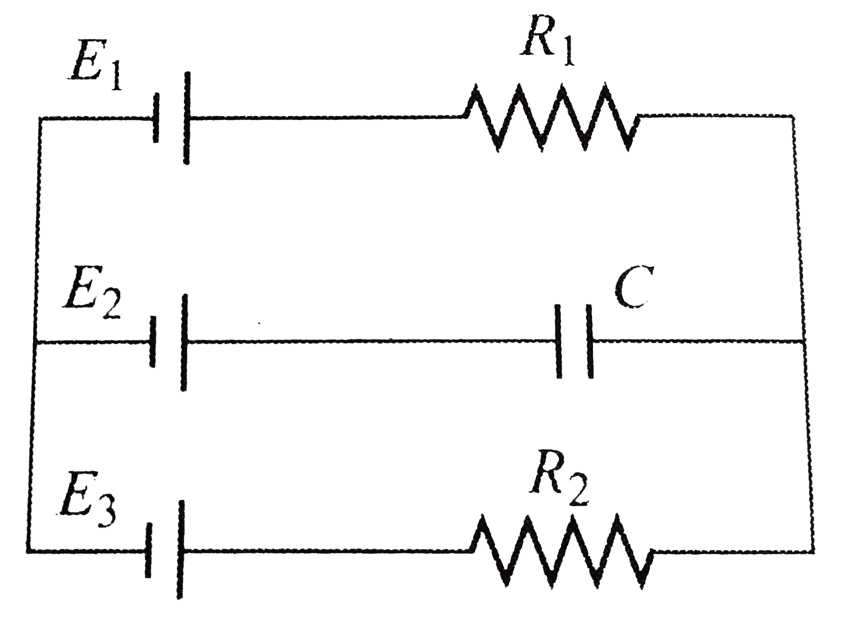
In the circuit shown , the batteries have emf E1=E2=1V,E3=2.5V, and the resistance R1=10Ω,R2=20Ω, Capacitance C=10μF. The charge on the left plate of the charge on the left plate of the capacitor C at steady state is
 A+2μCB−4μCC−5μCD+12μC
In the circuit shown in Fig. the emf of the sources is equal to ξ=5.0V and the resistances are equal to R1=4.0Ω and R2=6.0Ω. The internal resistance of the source equals R=1.10Ω. Find the currents flowing through the resistances R1 and R2.
 View Solution
Find the magnitude and direction of the current flowing through the resistance R in the circuit shown in Fig. if the emf's of the sources are equal to E1=1.5V and E2=3.7V and the resistances are equal to R1=10Ω,R2=20Ω,R=5.0Ω. The internal resistances of the sources are neglible.
 View Solution
Find a potentail difference φ1−φ2 between points 1 and 2 of the circuit shown in Fig if R11=10Ω,R2=20Ω,E1=5.0V, and E2=2.0V. The internal resisances of the current sources are negligible.
 View Solution
Three cells of emf, ε1=1.5V,ε2=2.0Vandε3=3.0V having internal resistance r1=0.30Ω,r2=0.4Ωandr3=0.6Ω respectively are connected in parallel. Find out the equivalent emf and the equivalent resistance of a cell which can replace this combination.
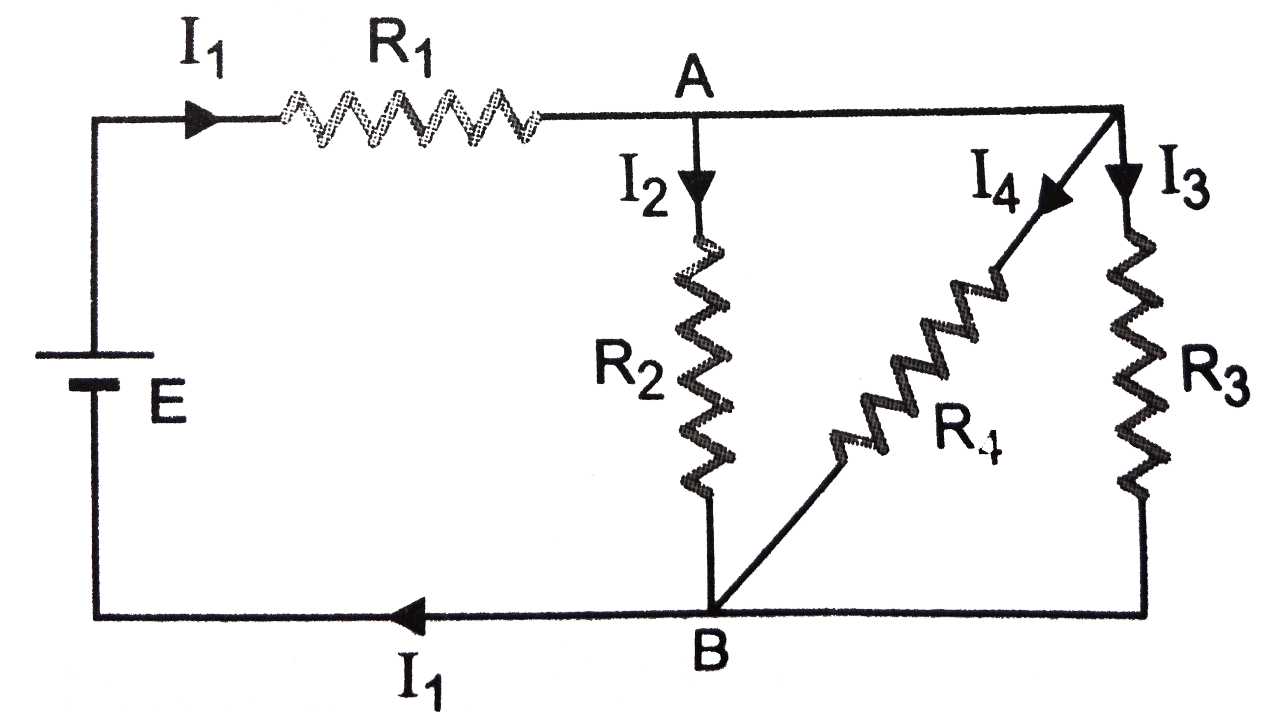
View SolutionIn the circuit R1=4Ω,R2=R3=15ΩR4=30ΩandE=10V Calculate the equivalent resistance of the circuit and current in each resistor
 View Solution
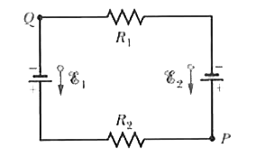
In Fig 27-56, the ideal batteries have emf emf12=200Vandε2=50V and the resistances are R1=3.0ΩandR2=2.0Ω. If the potential at P is 100 V, what is at at Q?
 View Solution
In the circuit shown in Fig. 4.19. R1=100Ω,R2=R3=50Ω,R4=75Ω and E=4.75 V. Work out the equivalent resistance of the circuit and the current in each resistor.
View Solution

