In Fig 27-56, the ideal batteries have emf emf12=200Vandε2=50V and the resistances are R1=3.0ΩandR2=2.0Ω. If the potential at P is 100 V, what is at at Q? 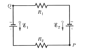
The correct Answer is:−40V
Step by step video, text & image solution for In Fig 27-56, the ideal batteries have emf emf_(1)2=200V and epsi_(2)=50V and the resistances are R_(1)=3.0 Omega and R_(2)=2.0 Omega. If the potential at P is 100 V, what is at at Q? by Physics experts to help you in doubts & scoring excellent marks in Class 12 exams.
Updated on:21/07/2023Topper's Solved these Questions
- CIRCUITSBOOK - RESNICK AND HALLIDAYCHAPTER - CIRCUITSEXERCISE - Practice Questions (Single Correct Choice Type)
33 Videos
- CIRCUITSBOOK - RESNICK AND HALLIDAYCHAPTER - CIRCUITSEXERCISE - Practice Questions (More than One Correct Choice Type)
12 Videos
- CIRCUITSBOOK - RESNICK AND HALLIDAYCHAPTER - CIRCUITSEXERCISE - Checkpoints
7 Videos
- CENTER OF MASS BOOK - RESNICK AND HALLIDAYCHAPTER - CENTER OF MASS EXERCISE - Practice Questions (Integer )
4 Videos
- CIRCULAR MOTIONBOOK - RESNICK AND HALLIDAYCHAPTER - CIRCULAR MOTIONEXERCISE - CHECK POINTS
6 Videos
Similar Questions
In Fig. 27-37, the ideal batteries have emfs ε1=12.0Vand=ε2=0.500ε1 and the resistances are each 4.00Ω. What is the current in (a) resistance 2 and (b) resistance 3?
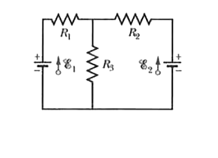
View SolutionFind a potential difference φA−φB between the plates of a capacitor C in the circuit shown in Fig, if the sources have emf'sE1=40V,E2=1.0V and the resistances are equal to R1=10Ω,R2=20Ω, and R3=30Ω. The internal resistances of the sources are negligble.

View Solution
Knowledge Check
Two ideal batteries of emfV1andV2 and three resistance R1R2andR3 are connected The current in resistance R2 would be zero if
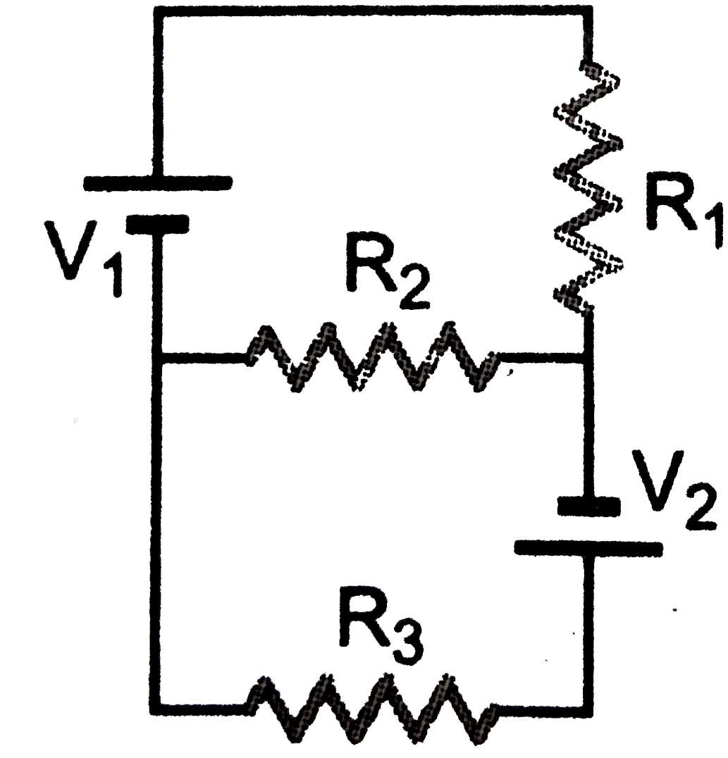 AV1=V2andR1=R2=R3BV1=V2andR1=2R2=R3CV1=2V2and2R1=2R2=R3D2V1=V2and2R1=R2=R3
In the circuit shown , the batteries have emf E1=E2=1V,E3=2.5V, and the resistance R1=10Ω,R2=20Ω, Capacitance C=10μF. The charge on the left plate of the charge on the left plate of the capacitor C at steady state is
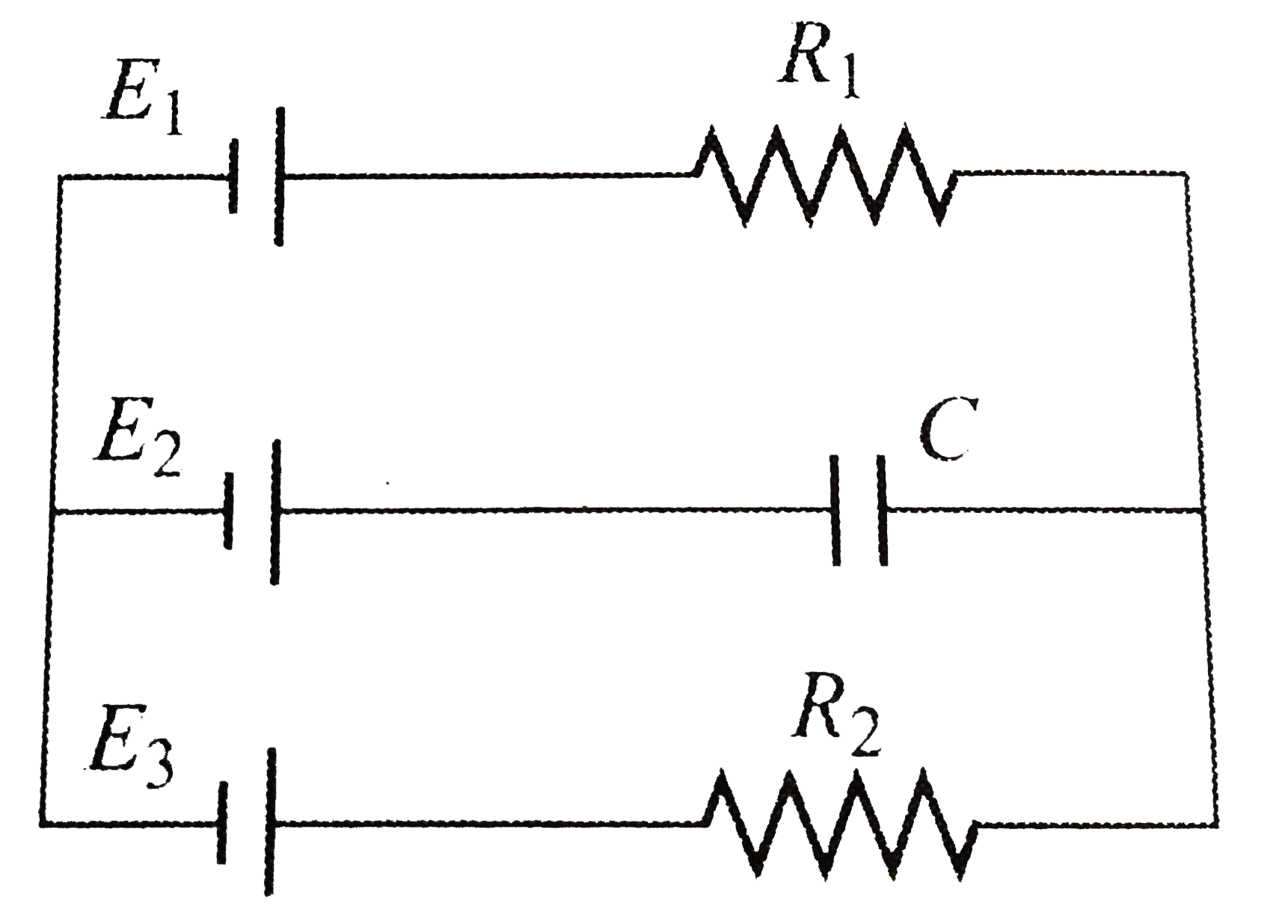 A+2μCB−4μCC−5μCD+12μC
In the circuit shown in Fig, the sources have emf'sξ1=1.5V,ξ2=2.0V,ξ3=2.5V , and the resistances are equal to R1=10Ω,R2=20Ω,R3=30Ω. The internal resistances of the sources are negligible. Find : ltbrtgt (a) the current flowing thorugh teh resistance R1 ,
(b) a potential differences φA−φB between the points A and B between the points A and B.

View SolutionFind the magnitude and direction of the current flowing through the resistance R in the circuit shown in Fig. if the emf's of the sources are equal to E1=1.5V and E2=3.7V and the resistances are equal to R1=10Ω,R2=20Ω,R=5.0Ω. The internal resistances of the sources are neglible.
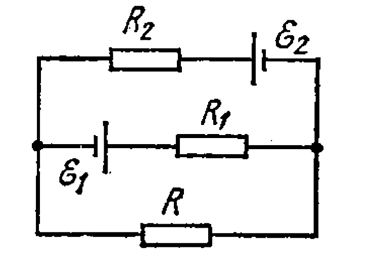
View SolutionIn the circuit shown in Fig. the emf of the sources is equal to ξ=5.0V and the resistances are equal to R1=4.0Ω and R2=6.0Ω. The internal resistance of the source equals R=1.10Ω. Find the currents flowing through the resistances R1 and R2.

View SolutionIn Fig. 27-51. battery 1 has emf ε1=12.0V and internal resistance r1=0.025Ω and battery 2 has emf2=12.0V and internal resistance r2=0.012Ω. The batteries are connected in series with an external resistance R. (a) What R value makes the terminal-to-terminal potential difference of one of the batteries zero? (b) Which battery is that?
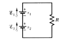
View SolutionIn Fig. 27-63, R1=100Ω,R2=50Ω, and the ideal batteries have emfs, ε1=6.0V,ε2=10V,andε3=4.0V. Find (a) the current in resistor 1, (b) the current in resistor 2, and (c) the potential difference between points a and b.
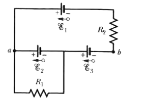
View SolutionIn Fig. 27-43, the current in resistance 6 is i6=2.80A the resistances are R1=R2=R3=2.00Ω,R4=16.0Ω,R5=8.00ΩandR6=4.00Ω. Wat is the emf of the ideal battery?

View Solution
