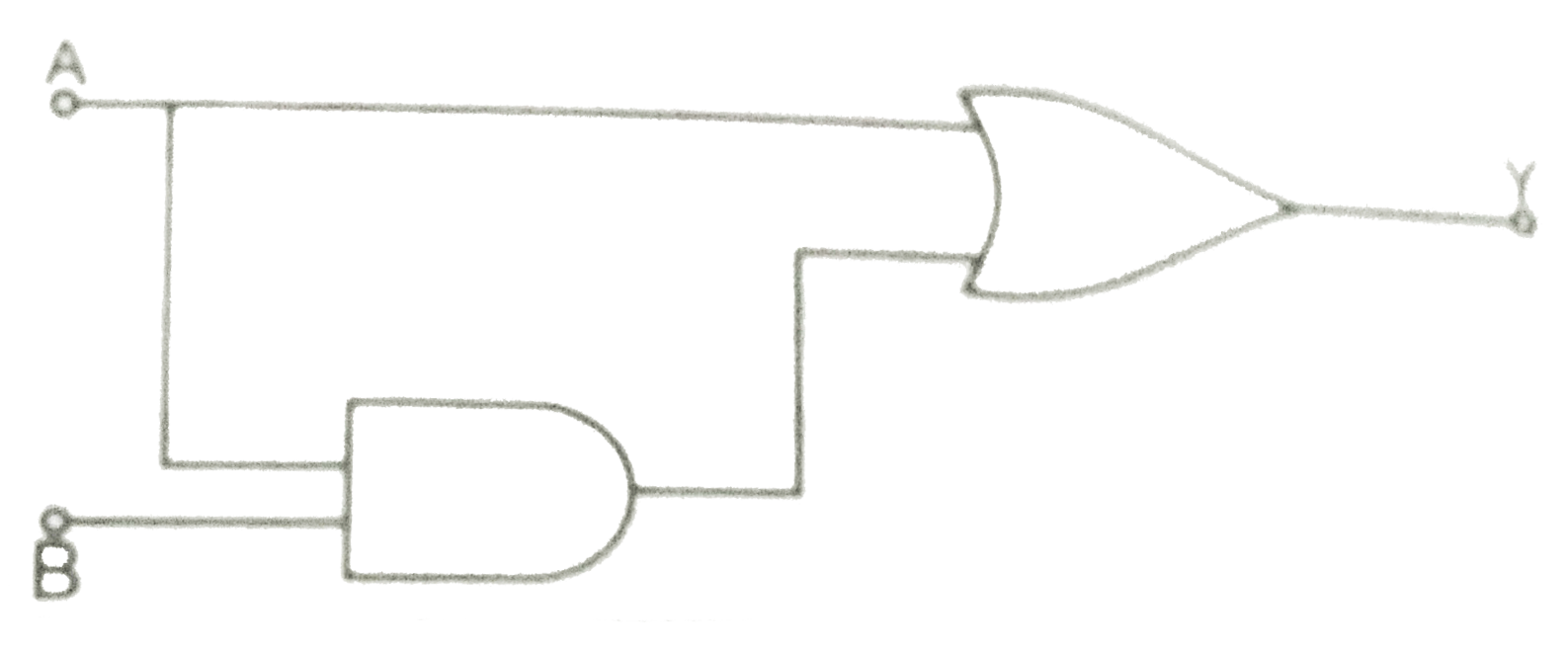
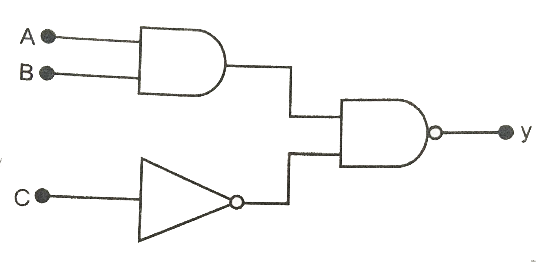
In the following circuit, the output Y for all possible inputs A and B is expressed by the truth table:

Video Solution
Text Solution
The correct Answer is:D
ABA+B¯¯¯¯¯¯¯¯¯¯¯A+B¯¯¯¯¯¯¯¯¯¯¯¯¯¯(A+B)+(¯¯¯¯¯¯¯¯¯¯¯A+B)Y000110011001101001111001

|
Topper's Solved these Questions
- SEMICONDUCTORSBOOK - CP SINGHCHAPTER - SEMICONDUCTORSEXERCISE - Exercises
140 Videos
- REFRACTION OF LIGHT BY PLANE SURFACESBOOK - CP SINGHCHAPTER - REFRACTION OF LIGHT BY PLANE SURFACESEXERCISE - Exercises
110 Videos
- THERMAL AND ELECTRIC EFFECT oF CURRENTBOOK - CP SINGHCHAPTER - THERMAL AND ELECTRIC EFFECT oF CURRENTEXERCISE - Exercises
101 Videos
Similar Questions
Knowledge Check
In the following circuit the output Y becomes zero for the inputs
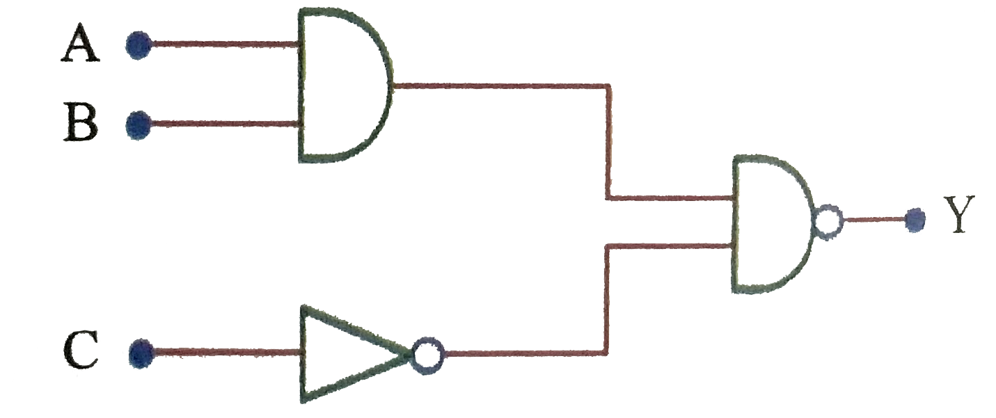 .AA=1,B=0,C=0BA=0,B=1,C=1CA=0,B=0,C=0DA=1,B=1,C=0
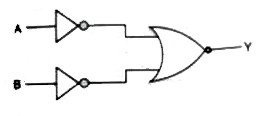
For the logic circuit shown, the truth table is
 A
A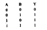 B
B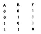 C
C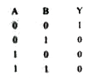 D
D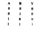
In AND gate, the output Y is 1 when the inputs A and B are:
AA=1, B=0BA=1, B=1CA=0, B=0DA=0, B=1
The Boolean expression of the output Y of the inputs A and B for the circuit shown in the fig.
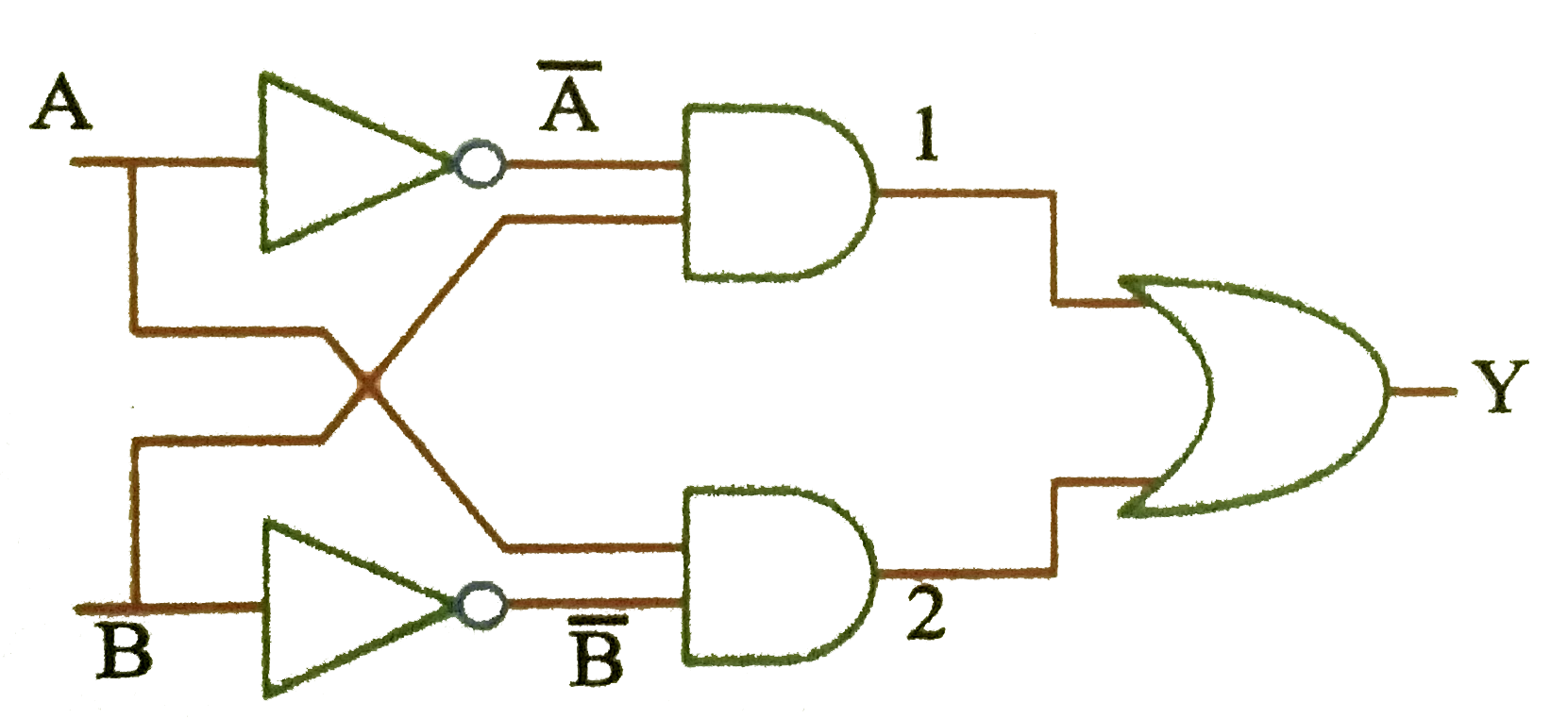 .
.
View SolutionIn the logic circuit shown in the figure, if input A and B are 0 to 1 respectively, the output at Y would be ‘x’
The value of x is _______

View SolutionWhich of the following is the truth table for the circuit below ?

View SolutionThe Boolean expression of the output Y of the inputs A and B for the circuit shown in the fig.
 .
.
View SolutionIn the circuit Fig. the output y becomes zero for the inputs
View Solution
