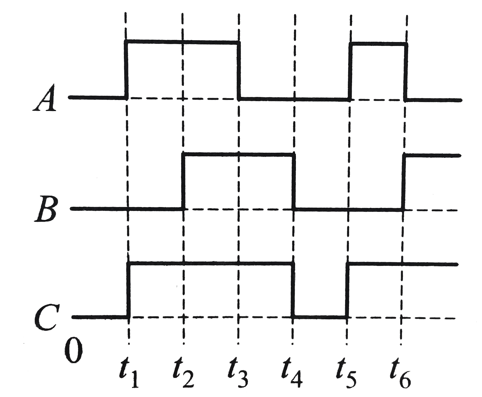
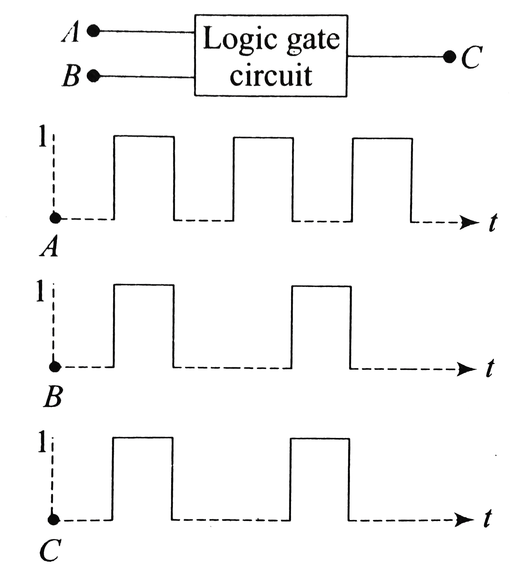
The figure shows a logic circuit with two inputs A and B and the output C. The voltage wave forms across A,B and C are as given. The logic circuit gate is
OR gate
NOT gate
AND gate
NAND gate
The correct Answer is:A
ABC000010111011
OR gate.
Topper's Solved these Questions
- BOOK - CP SINGHCHAPTER - SEMICONDUCTORSEXERCISE - Exercises140videos
SEMICONDUCTORS
- BOOK - CP SINGHCHAPTER - REFRACTION OF LIGHT BY PLANE SURFACESEXERCISE - Exercises110videos
REFRACTION OF LIGHT BY PLANE SURFACES
- BOOK - CP SINGHCHAPTER - THERMAL AND ELECTRIC EFFECT oF CURRENTEXERCISE - Exercises101videos
THERMAL AND ELECTRIC EFFECT oF CURRENT
Similar Questions
The following figure shows a logic gate circuit with two inputs A and B and the output C. The voltage waveforms of A, B and C are as shown below.
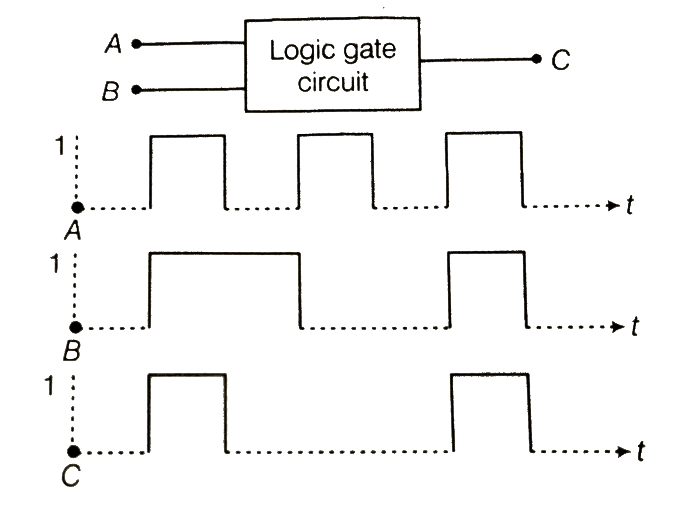
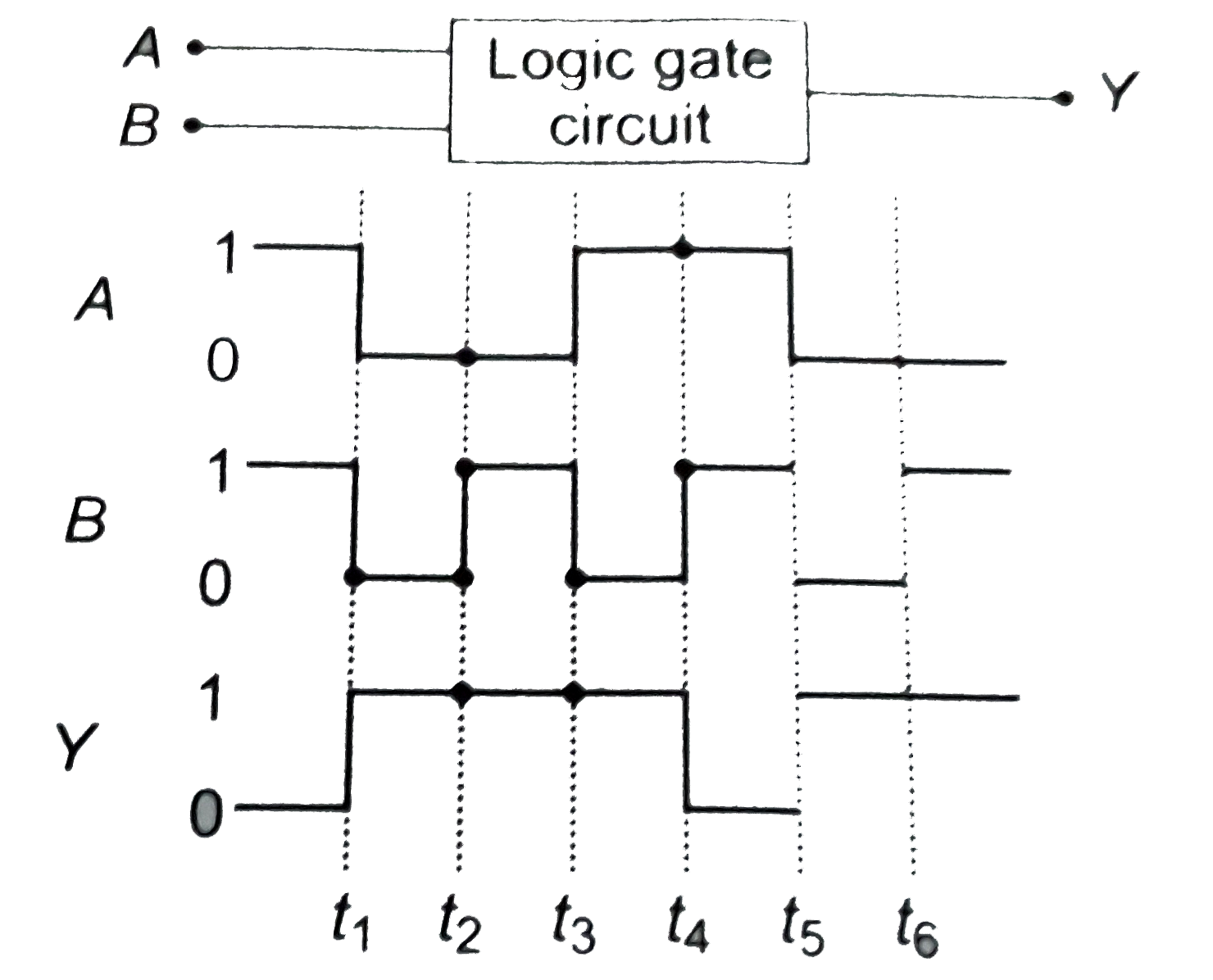
The logic circuit gate isView SolutionThe following figure shows a logic gate circuit with two inputs A and B and the output Y. The voltage waveforms of A,B and the output Y are as given
 View Solution
Knowledge Check
- Question 1 - Select One
The following figure shows a logic gate circuit with two inputs A and B and the output C. The voltage waveforms of A, B and C are as shown below
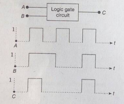
The logic circuit gate isAAND gateBNAND gateCNOR gateDOR gate - Question 2 - Select One
The following figure shows a logic gate circuit with two inputs A and B and the output C. The voltage waveforms of A, B and C are as shown below

The logic circuit gate isAAND gateBNAND gateCNOR gateDOR gate - Question 3 - Select One
The following shows a logic gate circuit with two inputs A and B and the output C. The voltage waveforms of A, B and C are as shown below.
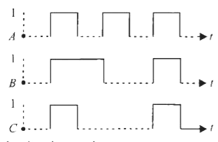
The logic circuit gate isAOR gateBAND gateCNAND gateDNOR gate
The following figure shows a logic gate circuit with two inputs A and B and the output Y. The voltage waveforms of A,B and Y are as given :
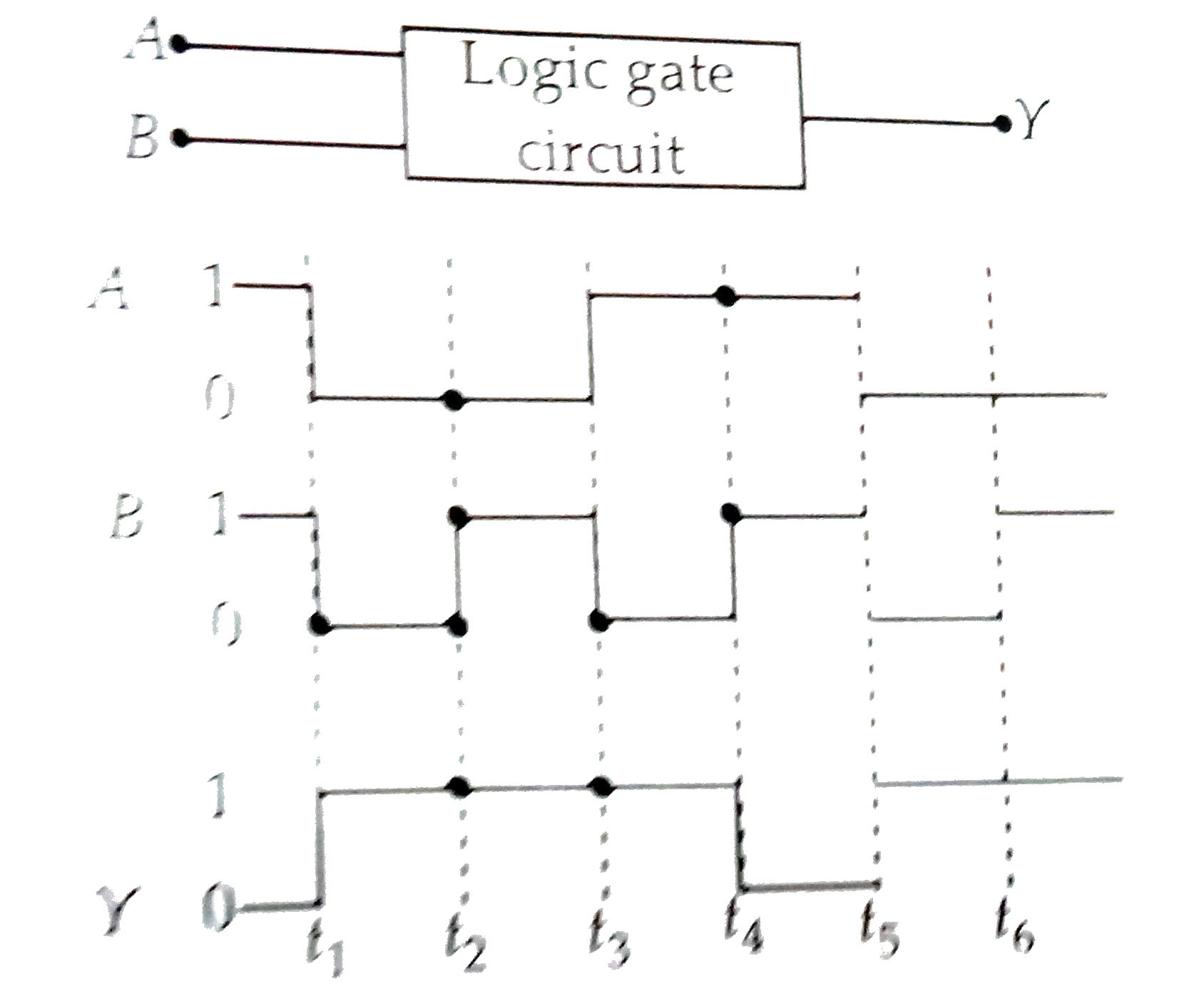
The logic gate isView SolutionFig, shows a logic gate circuit with two input A and B and the output C. The voltage wave form of A, B and C are as shown in Fig.The logic gate circuit is
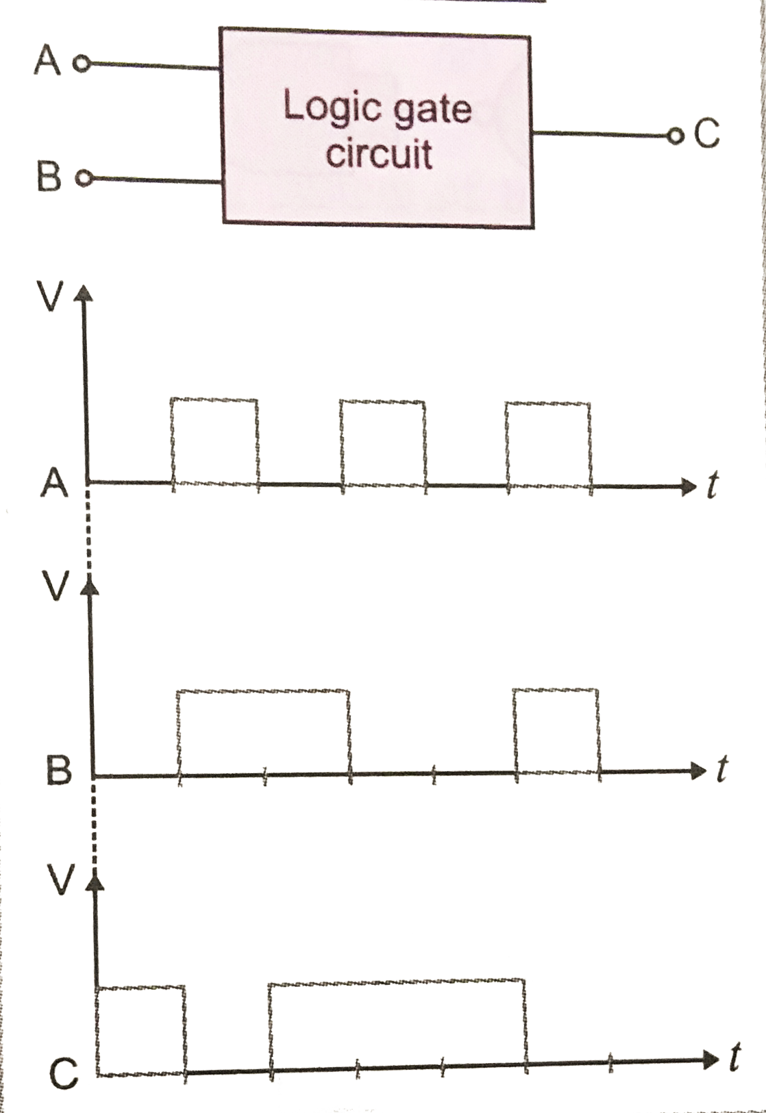 View Solution
The following figure shows a logic gate circuit with two inputs A and B and the output C. The voltage waveforms of A, B and C are as shown below-
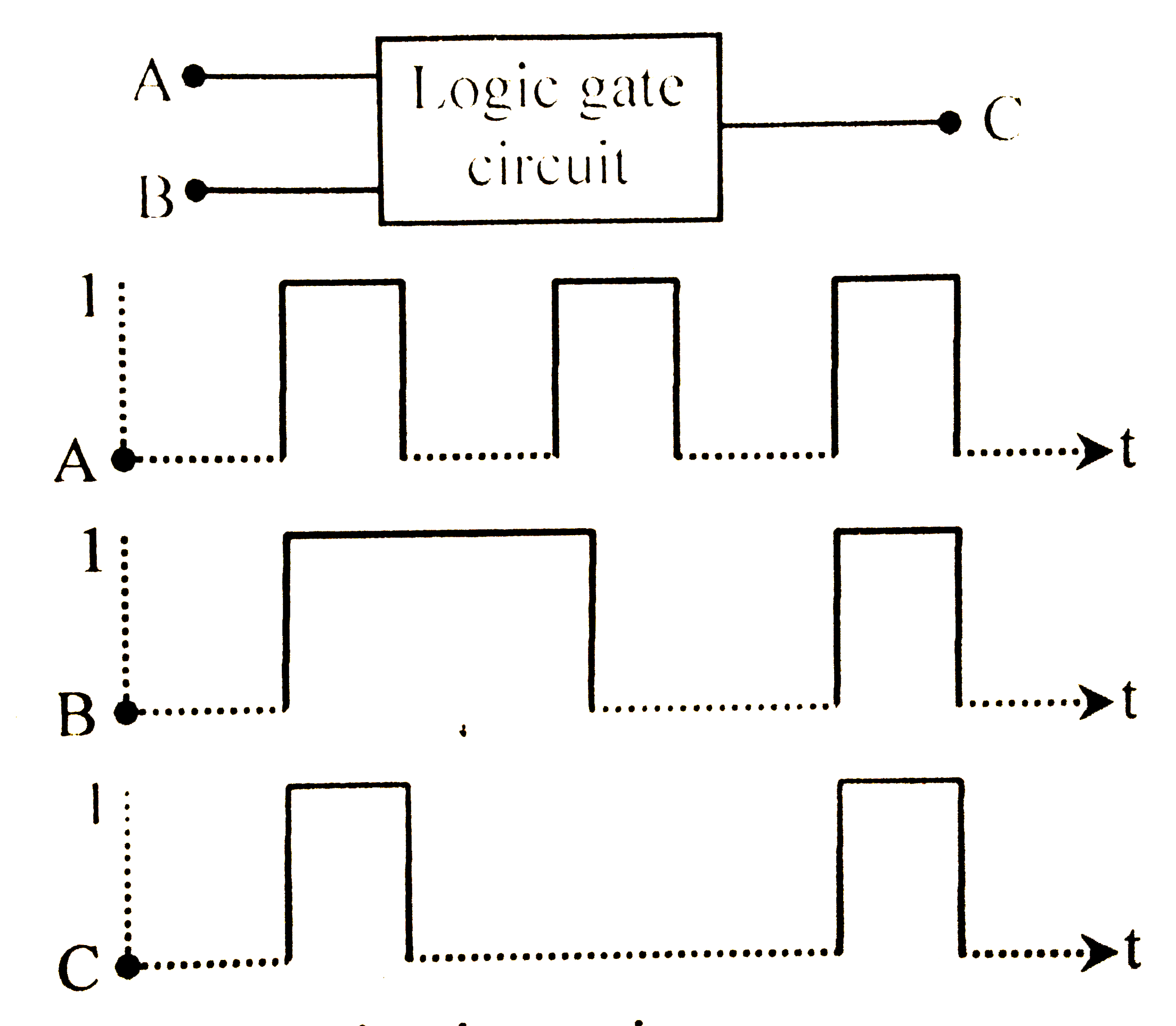 View Solution
The following figure shows a logic gate circuit with two inputs A and B and the output C. The voltage waveforms of A,B and C are as shown below
 View Solution
The following figure shows a logic gate circuit with two inputs A and B and the output Y. The voltage waveforms of A,B and the output Y are as given
 View Solution

