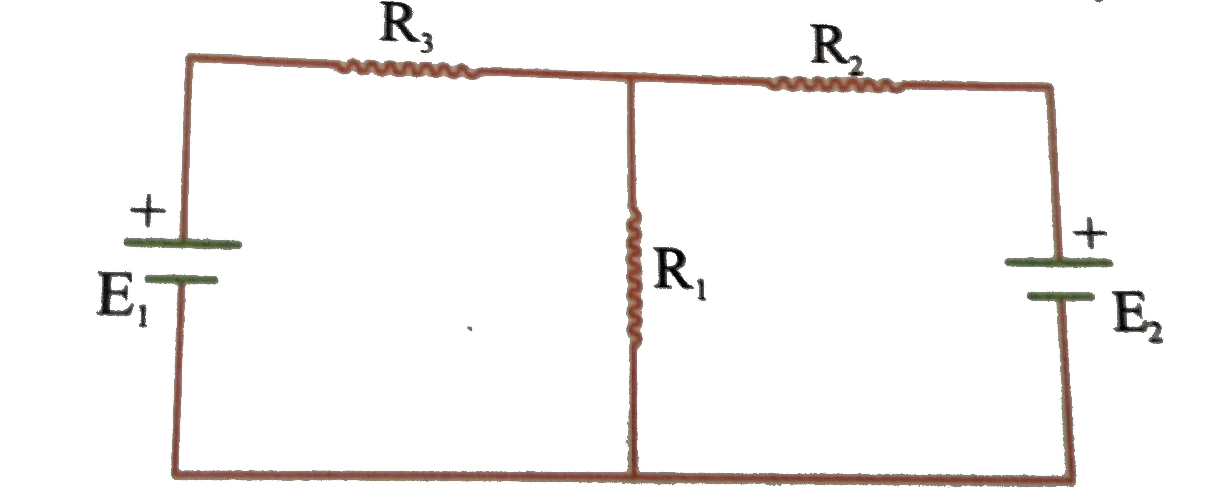
In the electrical network, shown in the diagram R1=5Ω,R2=2Ω,R3=3Ω and E1=2E2=10V, sources have negligible internal resistance. For this network,
The power generated in R1 is 6.4J/s
if the sources of e.m.f. E1 and E2 were physically inter changed, without changing the polarities, the power generated in R1 will be the same.
If the polarities of the sources E1 and E2 were both reversed,the power generated in R1 will be the same.
The ratio of the power generated in R2 and R3 1:30
The correct Answer is:A, C, D

(A). Power generated P is R1 is i21R1 now i1=VR1
where V is the potential at P, assuming that the negatives of the batteries are earthed. Simple application of Kirchhoff's junction and loop laws
yields i3=4531A,i2=−1031A
i1=i2+i3=3531A
V=R1i1=17531=5.7V
When R1=5Ω,R2=2Ω,R3=3Ω
Hence P=V2R1=(5.7)25=6.4Js
(B). Current in R1 will be different if the sources of emf E1 and E2 are interchanged.
(C). Current in R1 will be reversed in direction but numerically be the same hence P is not changed
(D). Ratio of powers in R2 and R3 is given by
P2P3=(V−5)2/R2(10−V)2/R3=(0.7)2/2(4.3)2/3≈130
Topper's Solved these Questions
- CURRENT ELECTRICITYBOOK - NARAYNACHAPTER - CURRENT ELECTRICITYEXERCISE - Level 5
42 Videos
- COMMUNICATION SYSTEMBOOK - NARAYNACHAPTER - COMMUNICATION SYSTEMEXERCISE - Level-II(H.W)
25 Videos
- DUAL NATURE OF RADIATION AND MATTERBOOK - NARAYNACHAPTER - DUAL NATURE OF RADIATION AND MATTEREXERCISE - ASSERTION AND REASON
15 Videos
Similar Questions
Find a potentail difference φ1−φ2 between points 1 and 2 of the circuit shown in Fig if R11=10Ω,R2=20Ω,E1=5.0V, and E2=2.0V. The internal resisances of the current sources are negligible.

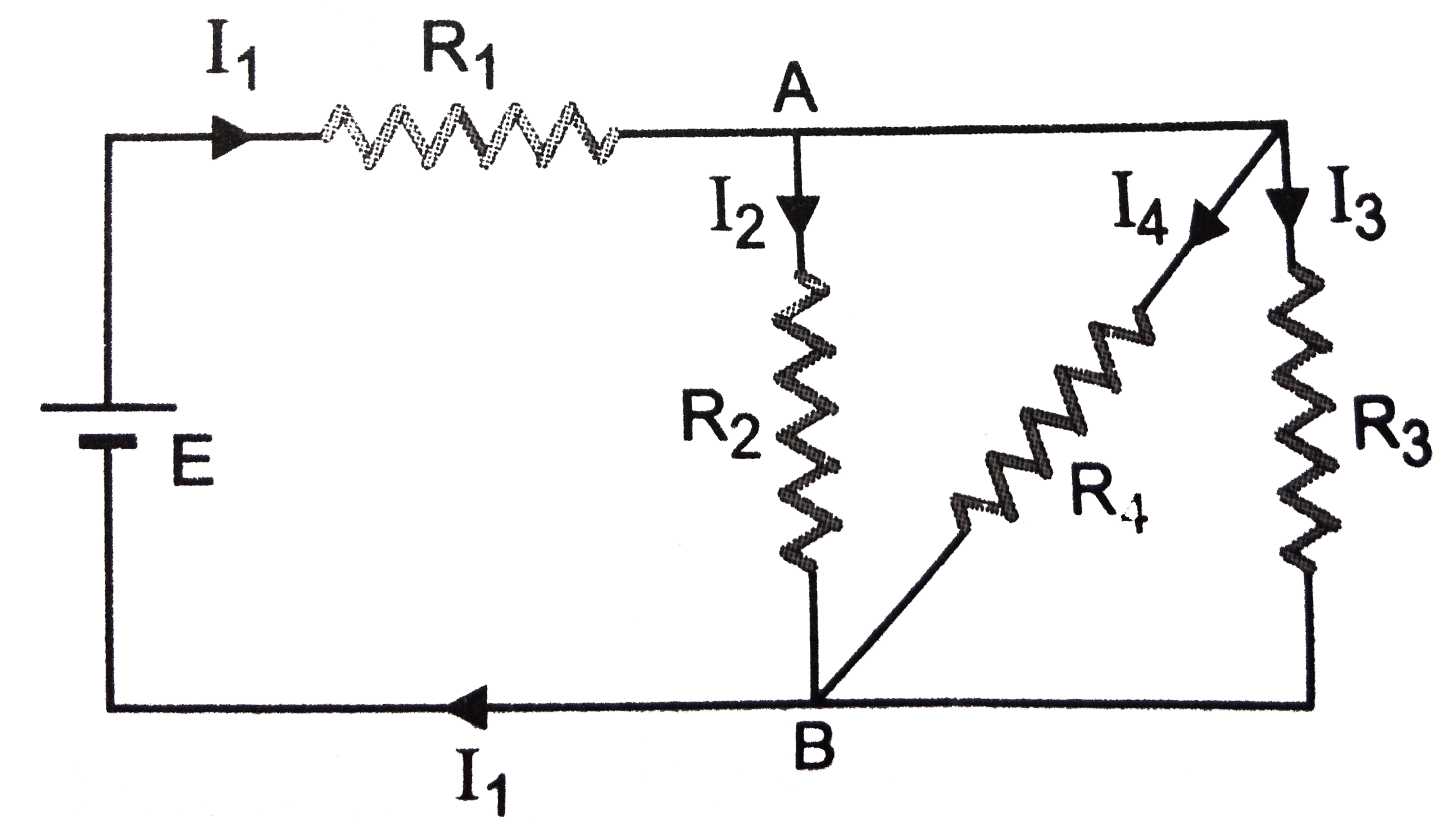
View SolutionIn the circuit R1=4Ω,R2=R3=15ΩR4=30ΩandE=10V Calculate the equivalent resistance of the circuit and current in each resistor
View Solution
Knowledge Check
A network of four unequal resistor R1,R2,R3 and R4 are connected in a network (see diagram) that contains a source of e.m.f E and an ammeter A. The source has negligible internal resistance. For this network,
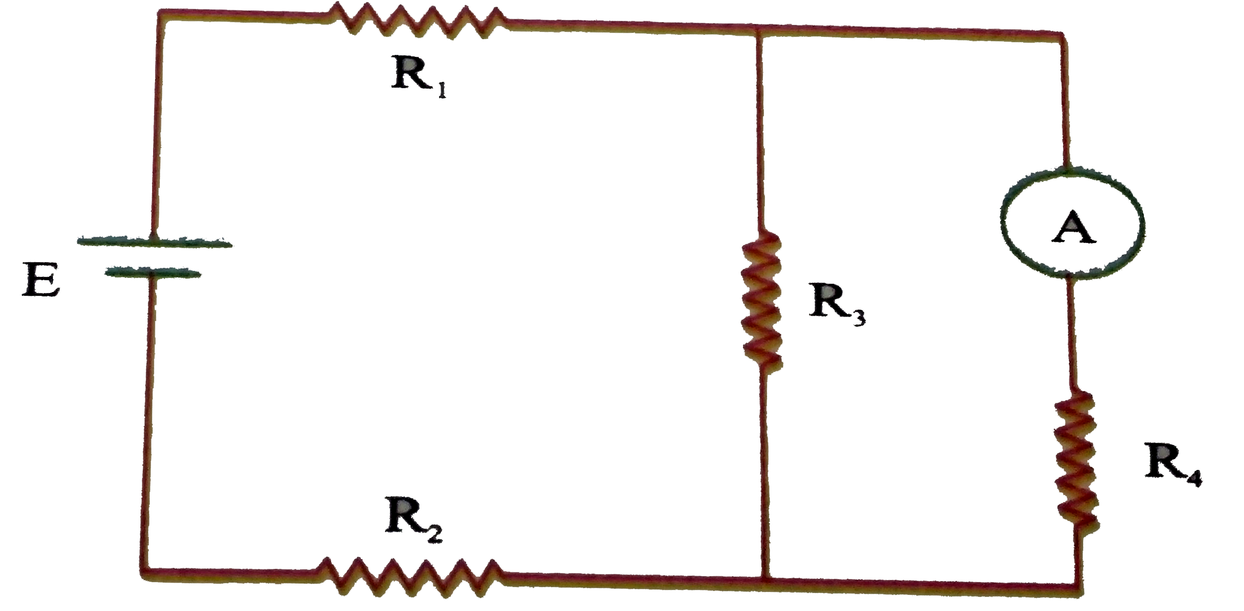 AIf R3>R4 the current in the resistor R3 will be less than that shown by the ammeterBif R3<R4 the current in the resistor R2 will be greater than that shown by the ammeterCif the source of e.m.f and the ammeter were physically interchanged in the network the ammeter will show the same current.DIf the resistors R2 and R1 were physically interchanged, the ammeter will show the same current.
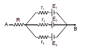
In the network shown the potential difference between A and B is (R=r1=r2=r3=1Ω,E1=3V,E2=2V,E3=1V)
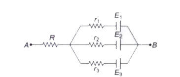 A1 VB2 VC3 VD4 V
In the given circuit, R1 = 10Ω R2=6Omega and E = 10V, then correct statement is
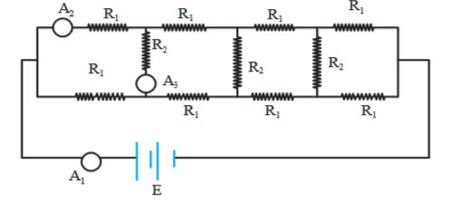 AEffective resistance of the circuit is 10ΩBR Reading of A1 is 1//2 amp.CReading of A2 is 1//2 ampDReading of A3 is 1//8 amp.
In the network shown the potential difference between A and B is R(=r1=r2=r3=1Ω,E1=3V,E2=2V,E3=1V)
View SolutionIn the circuit shown in Fig, the sources have emf'sξ1=1.5V,ξ2=2.0V,ξ3=2.5V , and the resistances are equal to R1=10Ω,R2=20Ω,R3=30Ω. The internal resistances of the sources are negligible. Find : ltbrtgt (a) the current flowing thorugh teh resistance R1 ,
(b) a potential differences φA−φB between the points A and B between the points A and B.

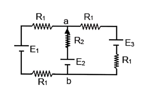
View SolutionIn the given network of ideal cells and resistors, R1=1.0Ω,R2=2.0Ω,E1=2V and E2=E3=4V. The potential difference between the point a and b is
View SolutionIn the given circuit, R1 = 10Ω R2=6Ω and E = 10V, then correct statement is

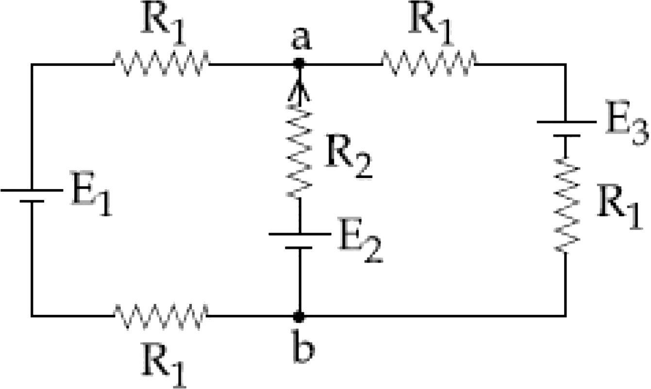
View SolutionFor the circuit shown, with R1=1.0Ω,R2=2.0Ω,E1=2V and E2=E3=4V, the potential difference between the points 'a' and 'b' is approximately (in V):
View Solution
