An inductor of inductance L=400 mH and resistor of resistance R1=2(Ω)andR2=2(Ω) are connected to a battery of emf E = 12 Vas shown in the figure. The internal resistance of the battery is negligible. The switch S is closed at time t =0. What is the potential drop across L as a function of time? After the steady state is reached, the switch is opened. What is the direction and the magnitude of current through R1 as a function of time?
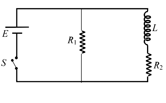
I1=ER1=122=6A,E=Ldl2dt+R2×l2
I2=I0(1−e−t/tc),⇒I0=ER2=122=6A
tc=LR=400×10−32=0.2,I26(1−e−t/0.2)
Potential drop across L
VL=E−R2I2=12−2×6(1−e−bt),=12e−5t
Topper's Solved these Questions
- ELECTRO MAGNETIC INDUCTIONBOOK - NARAYNACHAPTER - ELECTRO MAGNETIC INDUCTIONEXERCISE - C.U.Q 1
51 Videos
- ELECTRO MAGNETIC INDUCTIONBOOK - NARAYNACHAPTER - ELECTRO MAGNETIC INDUCTIONEXERCISE - Assertion & Reason
11 Videos
- ELECTRIC CHARGES AND FIELDSBOOK - NARAYNACHAPTER - ELECTRIC CHARGES AND FIELDSEXERCISE - EXERCISE -4
43 Videos
- ELECTRO MAGNETIC WAVESBOOK - NARAYNACHAPTER - ELECTRO MAGNETIC WAVESEXERCISE - LEVEL-II(H.W)
14 Videos
Similar Questions
An inductor of inductance L=400mH and resistors of resistances R1=2Ω and R2=2Ω are connected to a battery of emf E=12V as shown in the figure. The internal resistance of the battery is negligible. The switch S is closed at time t=0.
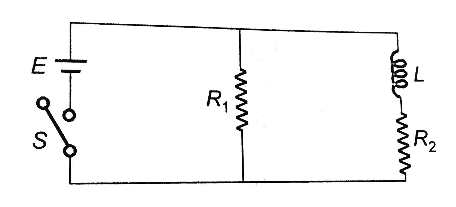
What is the potential dro across L s a function of time? After the steady state is reached, the switch is opened. What is the direction ad the magnitude of current throough R1 as a function of time?
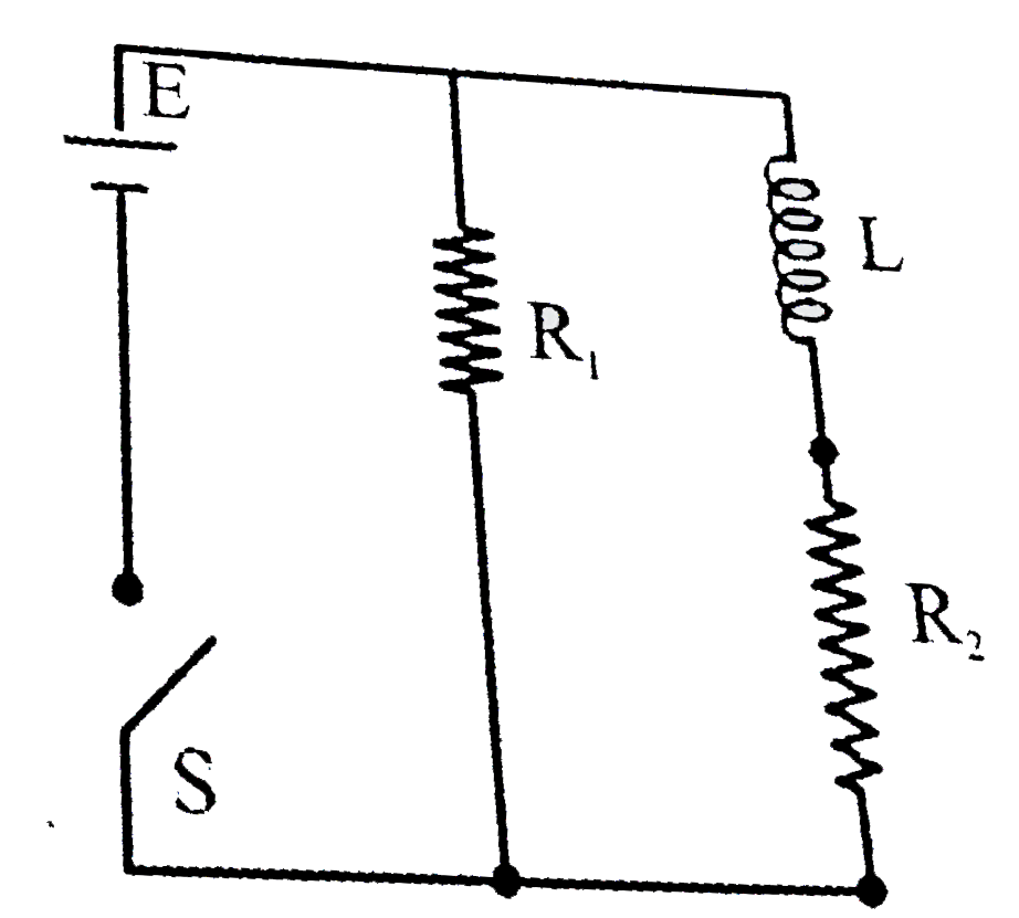
View SolutionAn inductor of inductance L = 400 mH and resistors of resistance R1=2Ω and R2=2Ω are connected to a battery of emf 12 V as shown in the figure. The internal resistance of the battery is negligible. The switch S is closed at t=0. The potential drop across L as a function of time is
View Solution
Knowledge Check
An inductor of inductance L = 400 mH and resistors of resistance R1=2Ω and R2=2Ω are connected to a battery of emf 12V as shown in the figure.The internal resistance of the battery is negligible.The switch S is closed at t = 0.The potential drop across L as a function of time is
 A12te−3tVB6(1−e−t0.2)VC12e−5tVD6e−5tV
An inductor of inductance L = 400 mH and resistors of resistance R1=2Ω and R2=2Ω are connected to a battery of emf 12 V as shown in the figure. The internal resistance of the battery is negligible. The switch S is closed at t=0. The potential drop across L as a function of time is
 A12te−3tVB6(1−e−t/0.2)VC12e−5tVD6e−5tV
An inductor of inductance L = 400 mH and resistors of resistance R1=2Ω and R2=2Ω are connected to a battery of emf 12 V as shown in the figure. The internal resistance of the battery is negligible. The switch S is closed at t=0. The potential drop across L as a function of time is
 A12te−31VB6(1−e−t/0.2)VC12e−5tVD5e−5tV
An inductor of self-inductance L and resistor of resistance R are connected in series to a battery of emf E and negligible resistance.Calculate the maximum rate at which energy is stored in the inductor.
View SolutionCalculate the steady state current in the 2Ω resistor, shown in figure. The internal resistance of the battery is negligible and the capacitance of the capacitor C is 0.2μF.
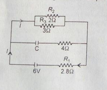
View SolutionCalculate the steady state current in the 2Ω resistor, shown in figure. The internal resistance of the battery is negligible and the capacitance of the capacitor C is 0.2μF.

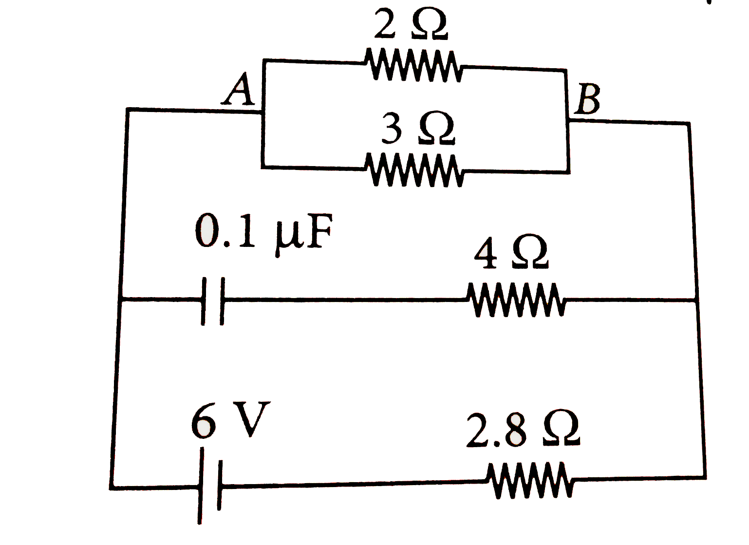
View SolutionThe steady state current in a 2Ω resistor when the internal resistance of the battery is negligible and the capacitance of the condenser is 0.1μF is
View SolutionA 4μF capacitor is connected to a battery of emf 24V. Through a resistance of 5MΩ and a switch which is kept open initially. Internal resistance of the battery is negligible. Switch is closed at t=0. Potential difference across capacitor and resistor at t=0 are respectively.
View Solution
