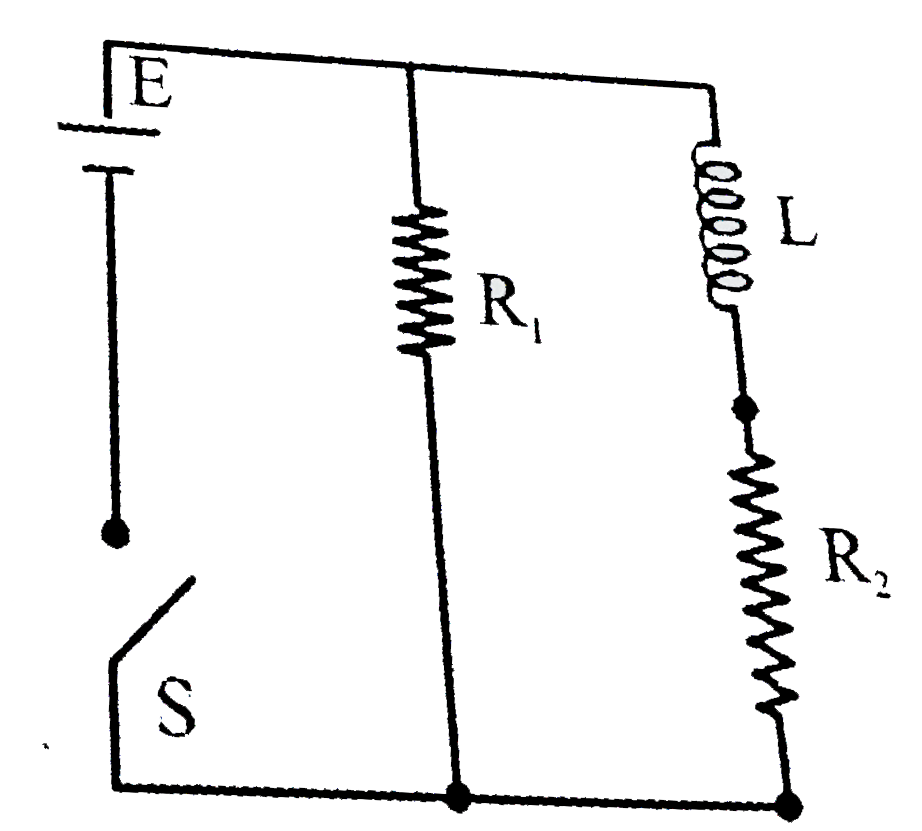
An inductor of inductance L=400mH and resistors of resistances R1=2Ω and R2=2Ω are connected to a battery of emf E=12V as shown in the figure. The internal resistance of the battery is negligible. The switch S is closed at time t=0.
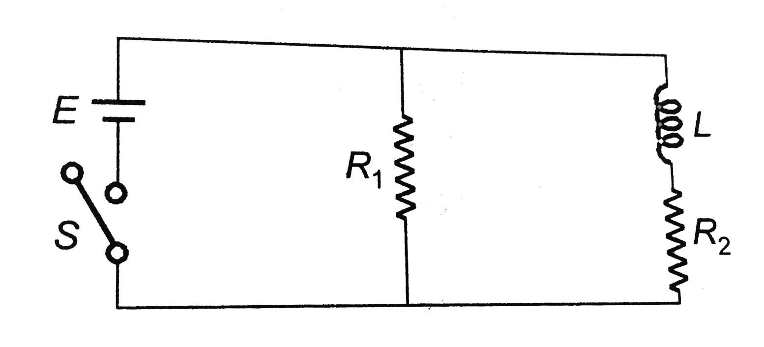
What is the potential dro across L s a function of time? After the steady state is reached, the switch is opened. What is the direction ad the magnitude of current throough R1 as a function of time?
a. Given R1=R2=2Ω,E=12V and L=400mH=0.4H.
Two parts of the circuit are in parallel with applied battery.
So, the givne circuit can be broken as
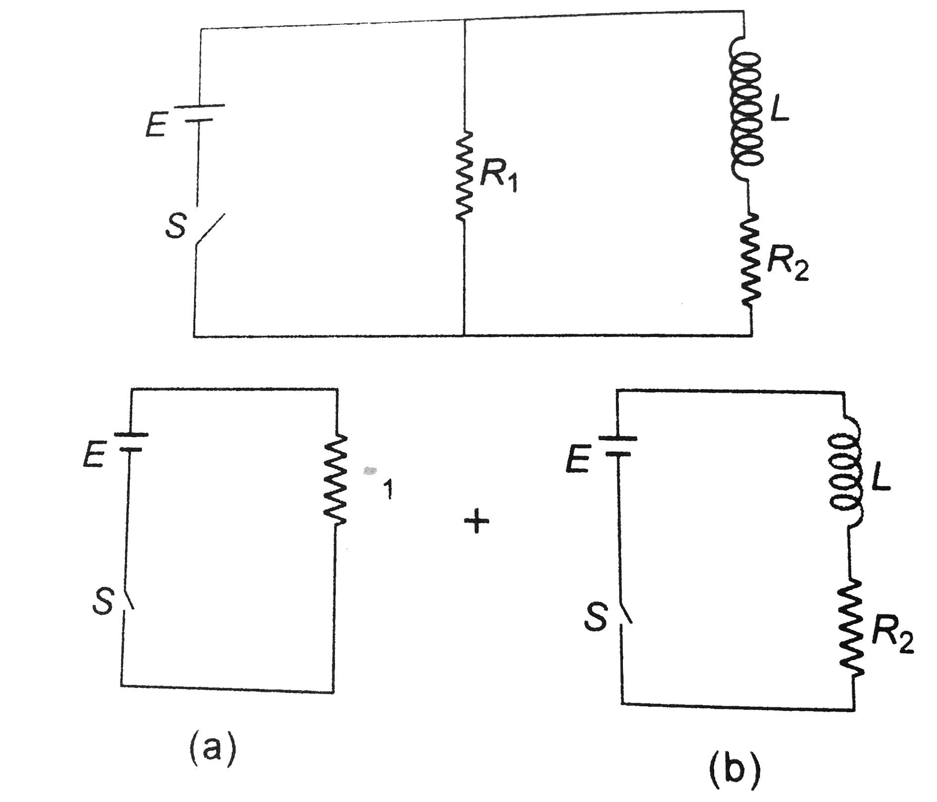
Now refere Figure b
This is a simple L−R circuit, whose time constant
τL=LR2=0.42=0.2s
and steady state current
i0=ER2=122=6A
Therefoe if switch S is closed at time t=0, then current in the circuit at any time t will be given
i(t)=(1−e−t/τL)
i(t)=6(1−e−t/0.2)
=6(1−e−5t)=i
Therefore, potential drop across L at any time t is
V=∣∣∣Ldidt∣∣∣=L(30e−5t)=(0.4)(30)e−5torV=12e−5tvolt
b. The steady state current in L or R2 is
i0=6A
Now, as soon as the switch is opened, current in R1 is reduced to zero immediately. But in L and R2 it decreases exponentially. the situtation is as follows:
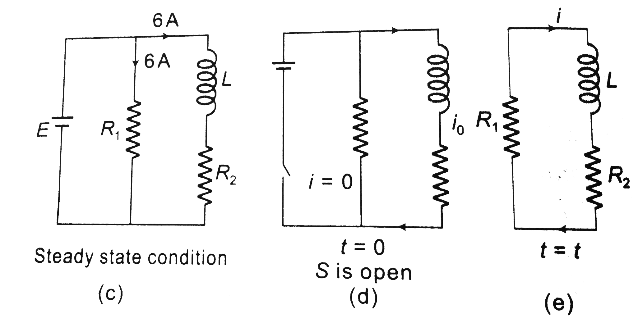
Refer figure
Time constant of this circuit would be
τ'=LLR1+R2=0.4(2+2)=0.1s
∴ Current through R1 at time t is
i=i0e−t/τL'=6e−t/0.1
ori=6−10tA
Direction of current in R1 is as shown in figure or clockwise.
Topper's Solved these Questions
- ELECTROMAGNETIC INDUCTIONBook:DC PANDEYChapter:ELECTROMAGNETIC INDUCTIONExercise:Example Type 4
Explore 2 Videos
- ELECTROMAGNETIC INDUCTIONBook:DC PANDEYChapter:ELECTROMAGNETIC INDUCTIONExercise:Example Type 5
Explore 2 Videos
- ELECTROMAGNETIC INDUCTIONBook:DC PANDEYChapter:ELECTROMAGNETIC INDUCTIONExercise:Example Type 2
Explore 2 Videos
- CURRENT ELECTRICITYBook:DC PANDEYChapter:CURRENT ELECTRICITYExercise:Medical entrances gallery
Explore 97 Videos
- ELECTROMAGNETIC WAVESBook:DC PANDEYChapter:ELECTROMAGNETIC WAVESExercise:Sec C
Explore 22 Videos
Similar Questions
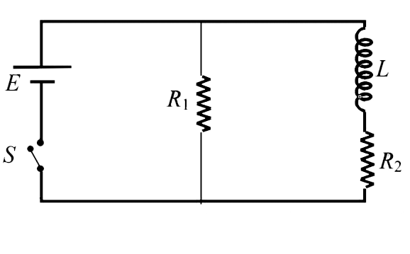
An inductor of inductance L=400 mH and resistor of resistance R1=2(Ω)andR2=2(Ω) are connected to a battery of emf E = 12 Vas shown in the figure. The internal resistance of the battery is negligible. The switch S is closed at time t =0. What is the potential drop across L as a function of time? After the steady state is reached, the switch is opened. What is the direction and the magnitude of current through R1 as a function of time?
View SolutionAn inductor of inductance L = 400 mH and resistors of resistance R1=2Ω and R2=2Ω are connected to a battery of emf 12 V as shown in the figure. The internal resistance of the battery is negligible. The switch S is closed at t=0. The potential drop across L as a function of time is
View Solution
Knowledge Check
An inductor of inductance L = 400 mH and resistors of resistance R1=2Ω and R2=2Ω are connected to a battery of emf 12 V as shown in the figure. The internal resistance of the battery is negligible. The switch S is closed at t=0. The potential drop across L as a function of time is
 A12te−3tVB6(1−e−t/0.2)VC12e−5tVD6e−5tV
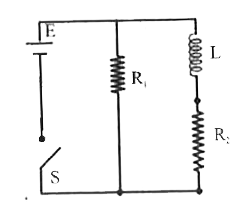
An inductor of inductance L = 400 mH and resistors of resistance R1=2Ω and R2=2Ω are connected to a battery of emf 12V as shown in the figure.The internal resistance of the battery is negligible.The switch S is closed at t = 0.The potential drop across L as a function of time is
 A12te−3tVB6(1−e−t0.2)VC12e−5tVD6e−5tV
An inductor of inductance L = 400 mH and resistors of resistance R1=2Ω and R2=2Ω are connected to a battery of emf 12 V as shown in the figure. The internal resistance of the battery is negligible. The switch S is closed at t=0. The potential drop across L as a function of time is
 A12te−31VB6(1−e−t/0.2)VC12e−5tVD5e−5tV
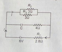
Calculate the steady state current in the 2Ω resistor, shown in figure. The internal resistance of the battery is negligible and the capacitance of the capacitor C is 0.2μF.
View SolutionCalculate the steady state current in the 2Ω resistor, shown in figure. The internal resistance of the battery is negligible and the capacitance of the capacitor C is 0.2μF.

View SolutionA 4 m long wire of resistance 8Ω is connected in series with a battery of emf 2V and a resistor of 7Ω. The internal resistance of the battery is 1Ω. What is the potential gradient along the wire ?
View SolutionA 4μF capacitor is connected to a battery of emf 24V. Through a resistance of 5MΩ and a switch which is kept open initially. Internal resistance of the battery is negligible. Switch is closed at t=0. Potential difference across capacitor and resistor at t=0 are respectively.
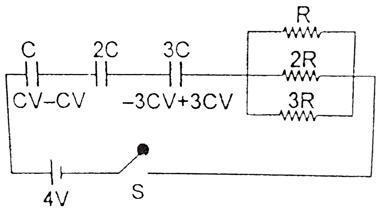
View SolutionThree capacitors (of capacitances C, 2C and 3C) and three resistors (of resistance R, 2R and 3R) are connected with a battery and switch S as shown in the figure. When switch S is open, charges on the capacitors are shown. Switch S is closed at t=0sec. The time constant of the circuit will be
View Solution
