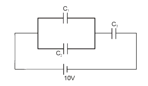
In Fig.25-25 a potentila difference V=100V is applied across a capacitor arragnement with capacitances C1=10.0μF,C2=5.00μFandC3=2.00μF What are (a) charge q3, (B) potential difference V3 and (c ) stored energy U3 for capacitor 3 (d) q1 (v) v1 and (f) U2 for capacitor 1, and (g) q3(h)V2 and (i) U2 for capacitor 2?
a)2.00×10⁻⁴b)100Vc)1.00×10⁻²Jd)3.33×10⁻⁴Ce)33.3Vf)5.55×10⁻³Jg)3.33×10⁻⁴Ch)66.7Vi)1.11×10⁻²J
Topper's Solved these Questions
- CAPACITANCEBOOK - RESNICK AND HALLIDAYCHAPTER - CAPACITANCEEXERCISE - PRACTICE QUESTIONS (SINGLE CORRECT CHOICE TYPE)
23 Videos
- CAPACITANCEBOOK - RESNICK AND HALLIDAYCHAPTER - CAPACITANCEEXERCISE - PRACTICE QUESTIONS (MORE THAN ONE CORRECT CHOICE TYPE)
12 Videos
- CAPACITANCEBOOK - RESNICK AND HALLIDAYCHAPTER - CAPACITANCEEXERCISE - CHECKPOINTS
4 Videos
- ALL ABOUT ATOMS BOOK - RESNICK AND HALLIDAYCHAPTER - ALL ABOUT ATOMS EXERCISE - CHECKPOINT
1 Videos
- CENTER OF MASS BOOK - RESNICK AND HALLIDAYCHAPTER - CENTER OF MASS EXERCISE - Practice Questions (Integer )
4 Videos
Similar Questions
In Fig. 25-25 a potential difference V=75.0 V is applied across a capacitor arrangement with capacitances C1=10.0μF,C2=5.00μF,andC3=15.0μF. What are (a) charge q3 (b) potential difference V3 and ( c) stored energy U3 for capacitor 3, (d) q1 (e) V1and(f)U1 for capacitor 1, and (g) q2(h)V2 and (i) U2 for capacitor 2?
View SolutionIn fig.25-25 a potential arrangement with capacitances applied across a capacitor arrangement with capacitances C1=10.0μF,C2=5.00μF,andC3=4.00μF. IF capacitor 3 undergoes electrical breakdown so that is becomes equivalent to conducting wire, then for capacitor 1 what are the increase in (a) charge, (b) potential difference, and ( c) stored energy
View Solution
Knowledge Check
A combination arrangement of the capacitors is shown in the figure
(i) C1=3μF,C2=6μF and C3=2μF then equivalent capacitance between 'a' and 'b' is :
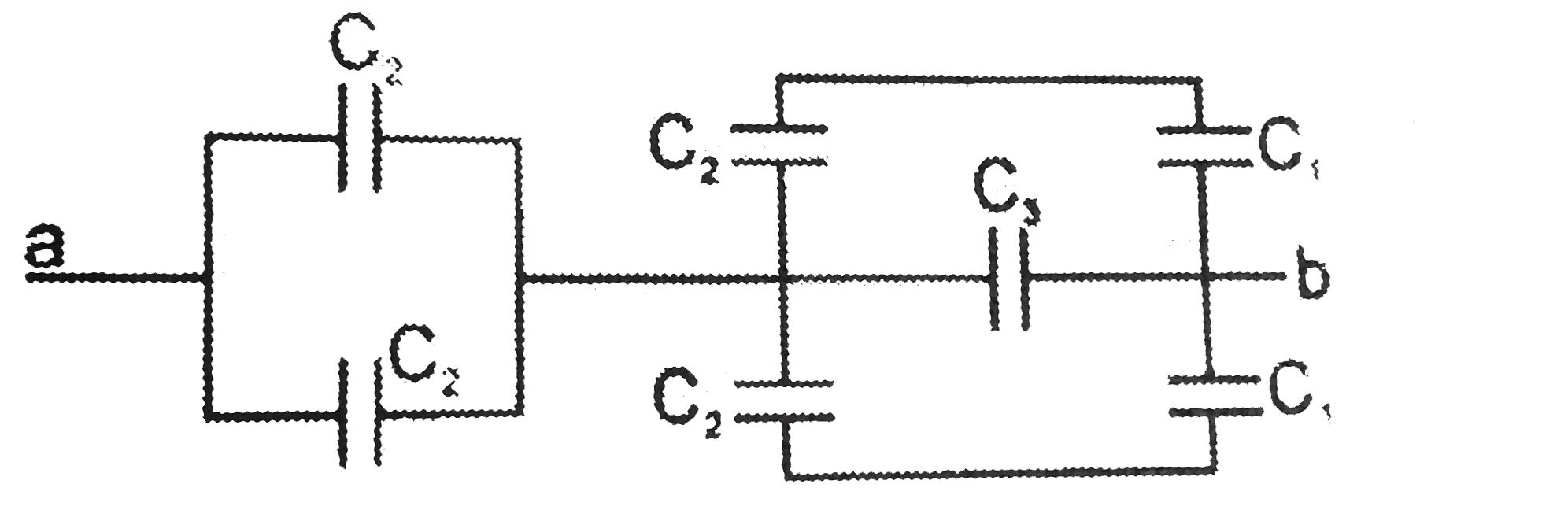 A4μFB6μFC1μFD2μF
A system of 2 capacitors of capacitance 2 μF and 4 μF is connected in series across a potential difference of 6 V. The electric charge and energy stored in the system are
A36μCand108μJB8μCand24μJC1μCand3μJD10μCand30μJ
In Fig, 25-26 , find the equivalent capacitance of the combination. C1 is 10.0μF,C2 is 8.00μF, and C3 is 4.00μF
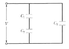
View SolutionIn Fig. 25-25 C1=10.0μF,C2=5.0μFandC3=4.0μF What is the change in their equivalent capacitance if (a) capacitors 1 and 2 are interchanged and (separately) (B) capacitors 1 and 3 are interchanged?
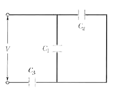
View SolutionIn Fig 25-33 the battery has a potential difference of V=12.0 V and the five capacitors each have a capacitance each have a capacitance of 10.0μF What is the charge on (a) capacitor 1 and (b) capacitor 2?
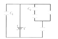
View SolutionA combination arrangement of the capacitors is shown in the figure
(i) C1=3μF,C2=6μF and C3=2μF then equivalent capacitance between 'a' and 'b' is :

View SolutionIn the circuit shown the capacitors areC1=15μF,C2=10μFandC2=25μF.Find
(i) The equivalent capacitance of the circuit
(ii) The charge on each capacitor and
(iii) The potential difference a across each capacitor.
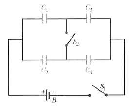
View SolutionFigure 25-43 shows a 24.0 V battery and four uncharged capacitors of capacitances C1=1.00μF,C2=2.00μFC3=3.00μFandC4=4.00μF IF only switch S1 is closed, what is the charge, on (a) capacitor 1 (b) capacitor 2 (c ) capacitor 3 and (d) capacitor 4? IF both switches are enclosed , what is the charge on (e) capacitors1.(f) capacitor 2, (g) capacitor 3, and (h) capacitor 4?
View Solution
