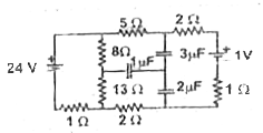
Analyse the circuit shown in the figure in steady state
Text Solution
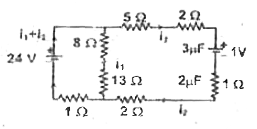
8i1+13i1+1(i1+i2)−24=0
22i1+i2=24ldots (1)
For right mesh,5I2+2i2+1+i2+2i2−13I1−8i1=0
or 10I2−2i1+1=0...(2)
From equations (1) and (2)
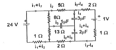
i1=1amp and, i2=2amp Now, considering current in different parts when capacitors were charging (e. when Lwwwisti 20 steady state was not reached) Current charging 2 muf capacitor= current charging 1 muF capacitor + current charging 3 muF capacitor If steady state charges on 1 muF and 3 muF capacitors are a q1μC and q2 μC respectively, then charge on2μF capacitor wil beq1+q2
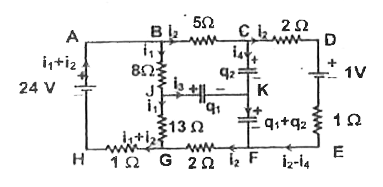
Hence, in steady state the circuit will be as shown in the figure
. Applying Kirchoff.s voltage law on mesh BCKJB
5i2+q23−q11−8i1=0 ...(3)512+99−81,=0(3)
For mesh JKFGJq1+q23−q11−8i=0...(4)
In equations (3) and (4), substituting. 11=1amp.i2=2amp
q1=4μC
q2=6μC
|
Topper's Solved these Questions
- CURRENT ELECTRICITYBOOK - FIITJEECHAPTER - CURRENT ELECTRICITYEXERCISE - SOLVED PROBLEMS (OBJECTIVE)
20 Videos
- CURRENT ELECTRICITYBOOK - FIITJEECHAPTER - CURRENT ELECTRICITYEXERCISE - Exercise
9 Videos
- CURRENT ELECTRICITYBOOK - FIITJEECHAPTER - CURRENT ELECTRICITYEXERCISE - Illustration
10 Videos
- COLLISION BOOK - FIITJEECHAPTER - COLLISION EXERCISE - (NUMERICAL BASED QUESTIONS)
4 Videos
- ELASTICITY AND WAVES BOOK - FIITJEECHAPTER - ELASTICITY AND WAVES EXERCISE - Assignment Problems (Objective) Level-II
15 Videos
Similar Questions
Knowledge Check
In the circuit shown in the figure, in steady state:

The charge on 5μF capacitor isA30μCB40μCC50μCD60μCIn the circuit shown in the figure, in steady state:

The current drawn from the battery isA2AB3AC4AD1AIn the circuit shown in the figure The steady state currents i1andi2 in the coils after the switch S is closed are
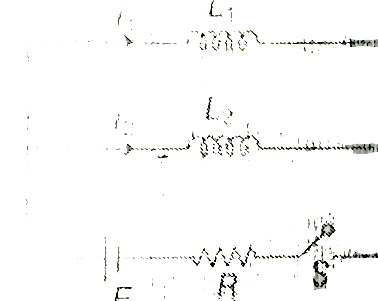 Ai1=EL2R(L1+L2)Bi1=EL1R(L1+L2)Ci2=EL2R(L1+L2)Di2=E√L1L2RL2
In the circuit shown in the figure The steady state currents i1andi2 in the coils after the switch S is closed are

View SolutionThe circuit shown in the Figure is in steady state. Find the rate of change of current through L immediately after the switch S is closed.
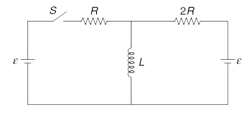
View SolutionFind the potential difference between the plates of the capacitor C in the circuit shown in figure-3.161 in steady state. The internal resistances of the cells are negligible.
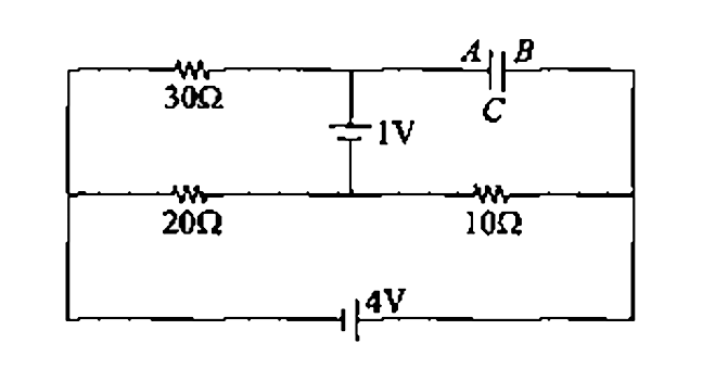
View SolutionThe power consumption by the circuit shown in figure at steady state is
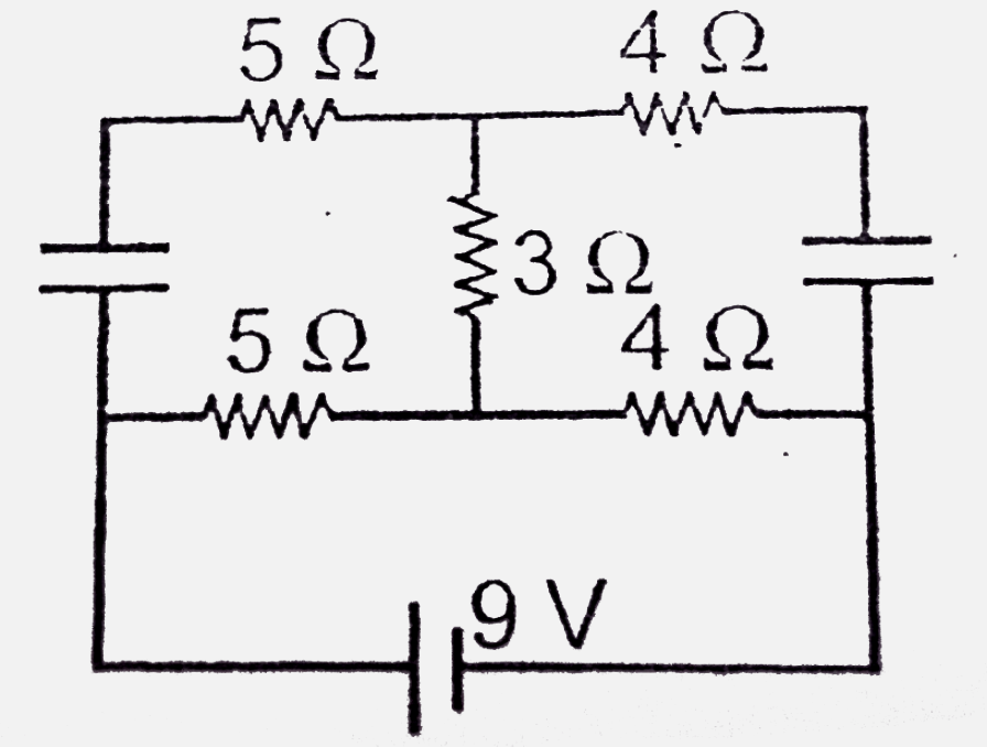
View SolutionThe power consumption by the circuit shown in figure at steady state is

View Solution
