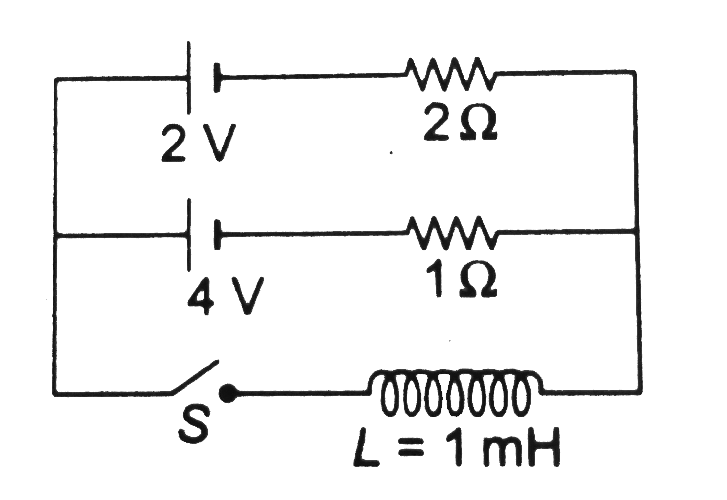
Initially switch 'S' was open and the circuit has achieved its steady state at t=0. Then , switch 'S' is sddenly closed. Find the current through resistance R as a function of time.
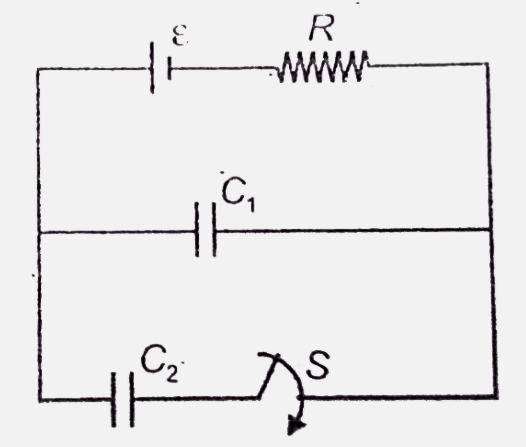
εC2(C1+C2)e−t/(C1+C2)R
Topper's Solved these Questions
- CURRENT ELECTRICITYBOOK - AAKASH INSTITUTECHAPTER - CURRENT ELECTRICITYEXERCISE - ASSIGNMENT SECTION-I(SUBJECTIVE TYPE QUESTIONS)
13 Videos
- COMMUNICATION SYSTEMS BOOK - AAKASH INSTITUTECHAPTER - COMMUNICATION SYSTEMS EXERCISE - ASSIGNMENT SECTION D (Assertion-Reason)
10 Videos
- DUAL NATURE OF RADIATION AND MATTER BOOK - AAKASH INSTITUTECHAPTER - DUAL NATURE OF RADIATION AND MATTER EXERCISE - ASSIGNMENT (SECTION-D)
10 Videos
Similar Questions
Knowledge Check
In the circuit diagram shown in figure, initially switch S is opened and the circuit is in steady state. At time t=0, the switch S is closed and the new steady state is reached after some time. Choose the correct option(s)
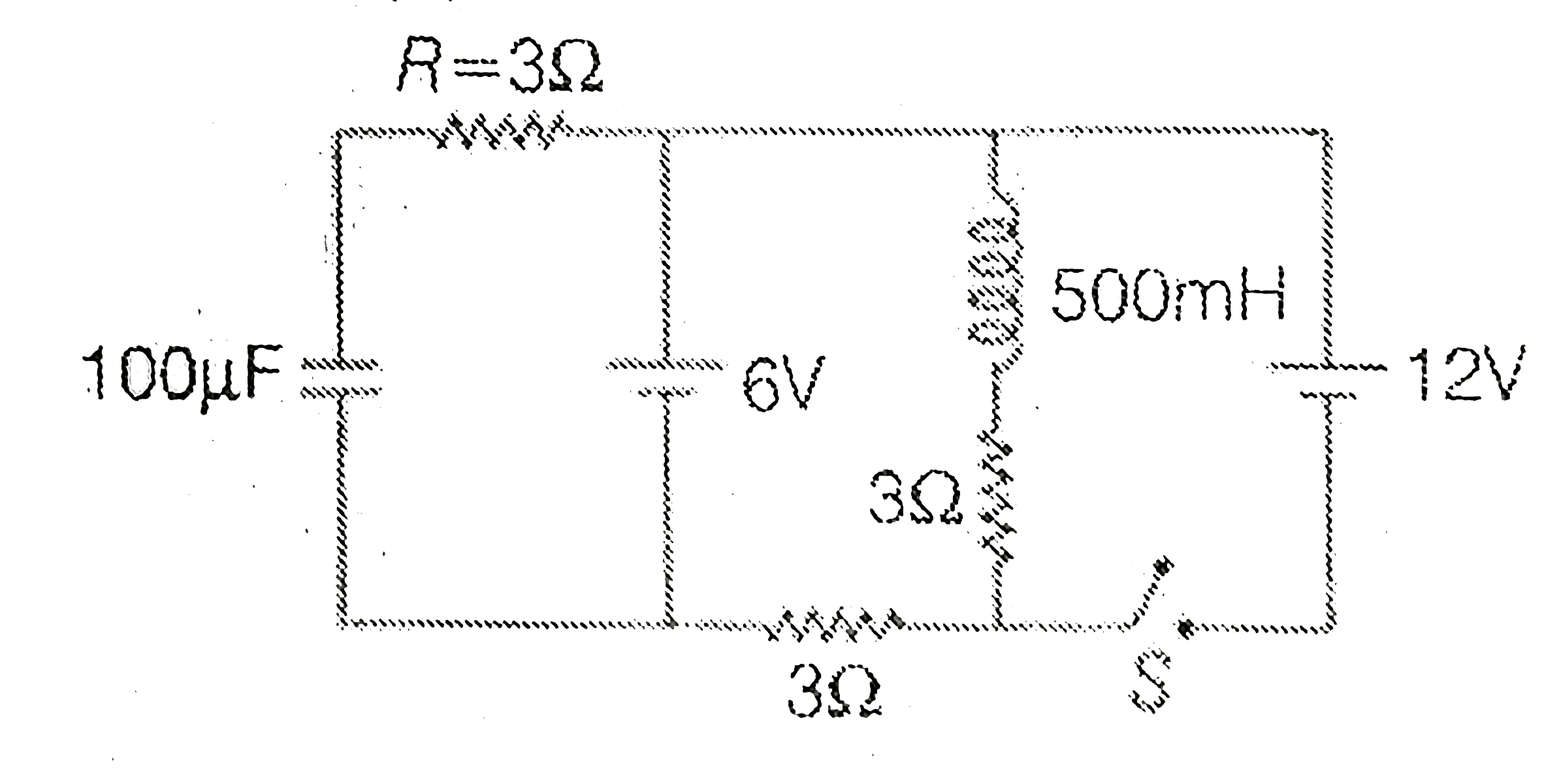 ACurrent in the indcutor when the circuit reaches the new steady state is 4A.BThe net change in the magnitic flux is the inductor is 1.5WbCThe net change in the magnetic flux in the conductor is 9volt when the circuit reaches the new steady state.DThe charge stored in the capacitor in the new steady state is 1.2mC
The circuit consists of two resistors (of resistance R1=20Ω and R2=10Ω), a capacitor (of capacitance C=10μF) and two ideal cells. In the circuit shown the capacitor is in steady state and the switch S is open
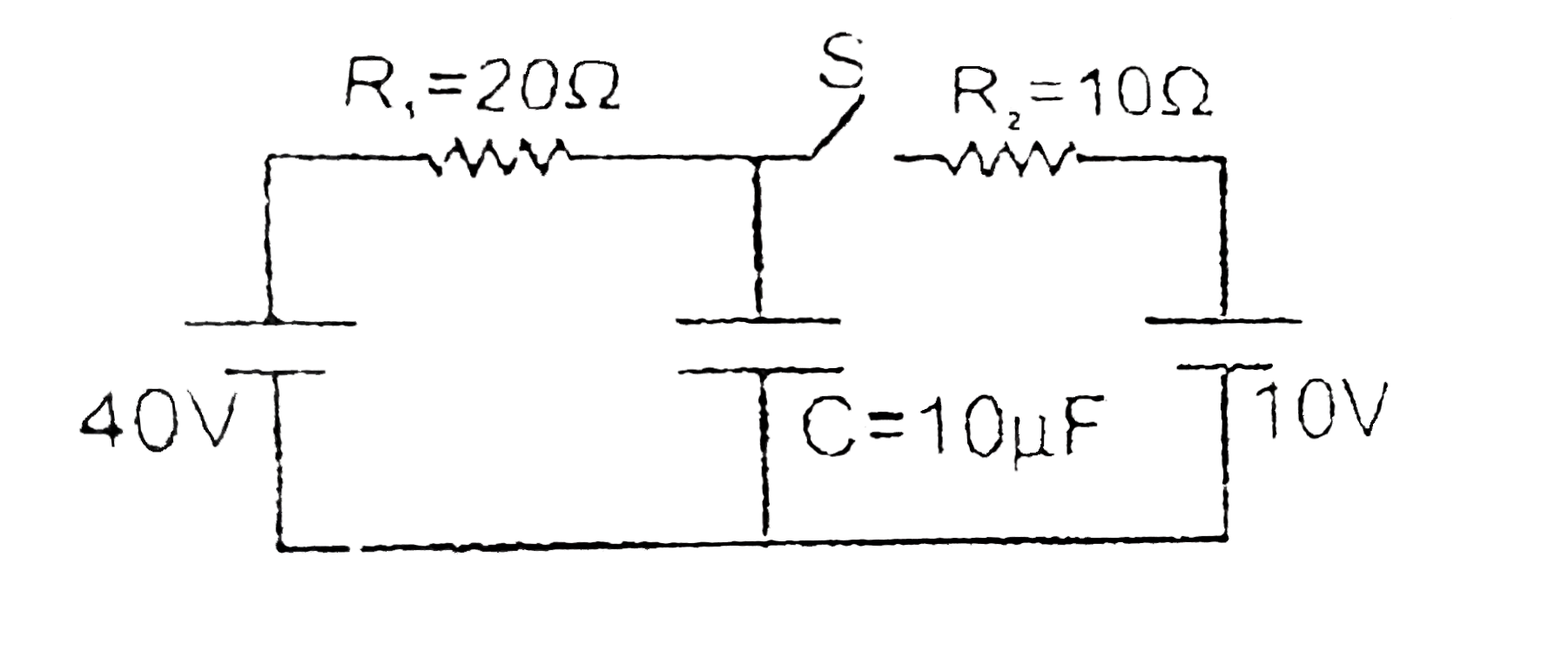
the circuit is in steady state with switch S closed. Now the switch S is opened. Just after the switch S is opened. the current through resistance R1 isA1 ampereB2 ampereC3 ampereD4 ampere
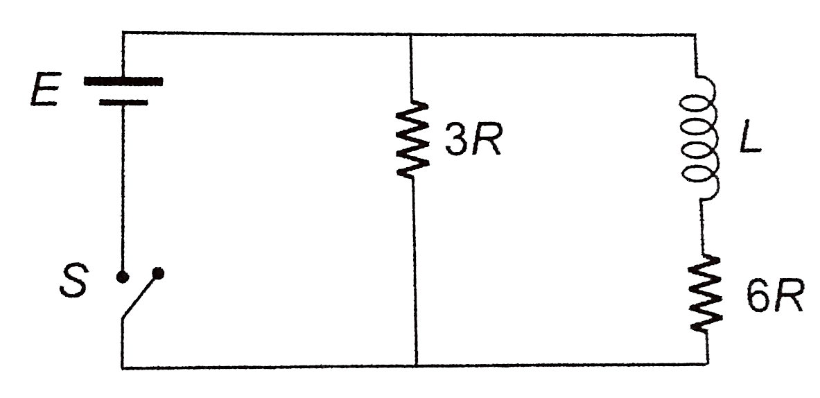
At t=0 , switch S is closed. Find time constant of the circuit and current through inductor as a function of time t .
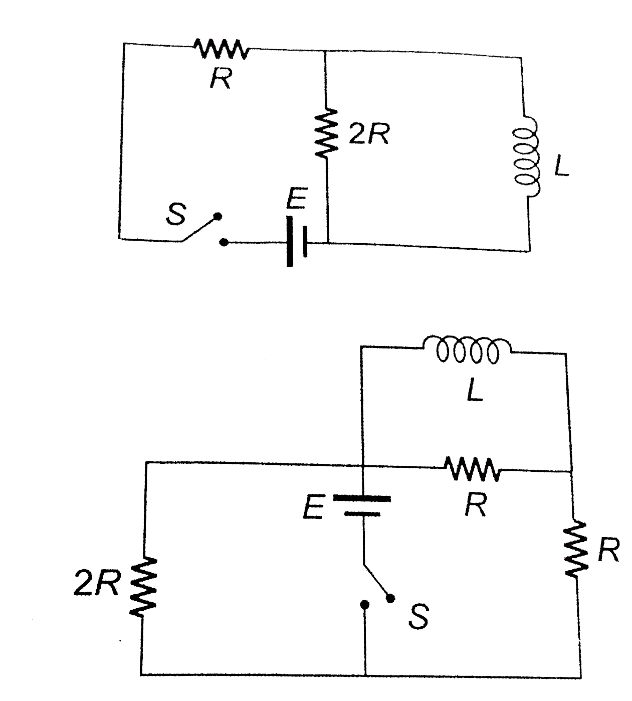
View SolutionIn the circuit diagram shown in figure, initially switch S is opened and the circuit is in steady state. At time t=0, the switch S is closed and the new steady state is reached after some time. Choose the correct option(s)

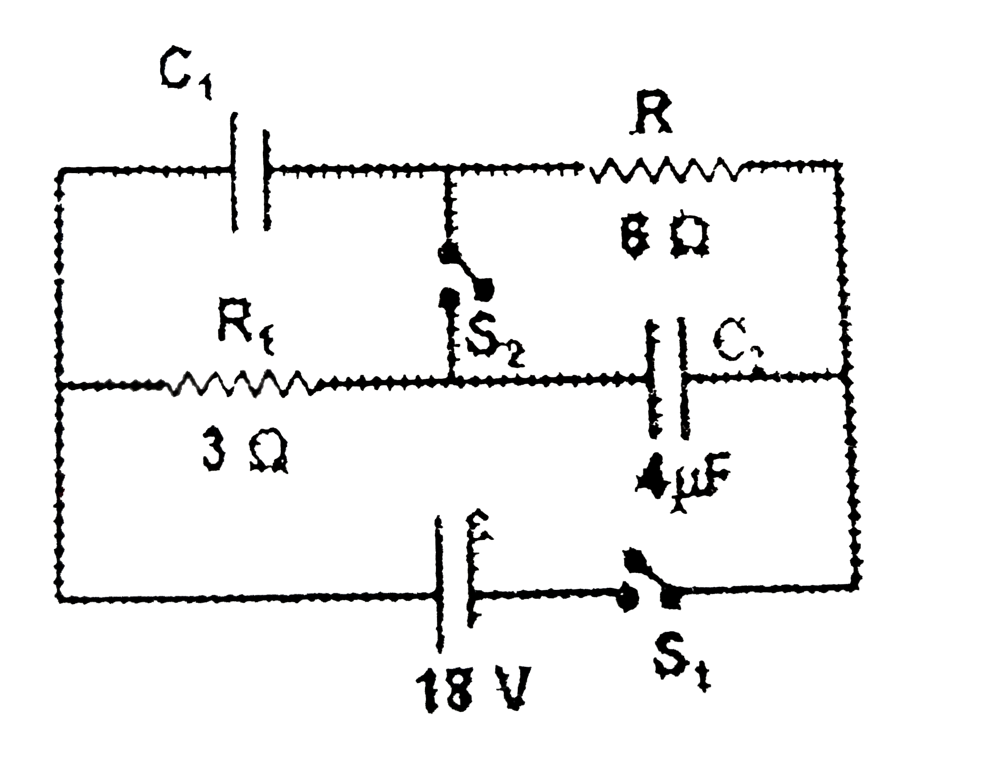
View SolutionConsider the shown network. Initially both swiches are open and the capacitor are uncharged. Both the switches are then closed simultaneously at t=0
(a) Obtain the current through switch S2 as function of time.
(b) If switch S2 is opened again after a long time interval, find the total heat that would dissipate in the resistor and the charge that would flow through switch S1 after S2 is opened?

View SolutionThe circuit consists of two resistors (of resistance R1=20Ω and R2=10Ω), a capacitor (of capacitance C=10μF) and two ideal cells. In the circuit shown the capacitor is in steady state and the switch S is open

the circuit is in steady state with switch S closed. Now the switch S is opened. Just after the switch S is opened. the current through resistance R1 is
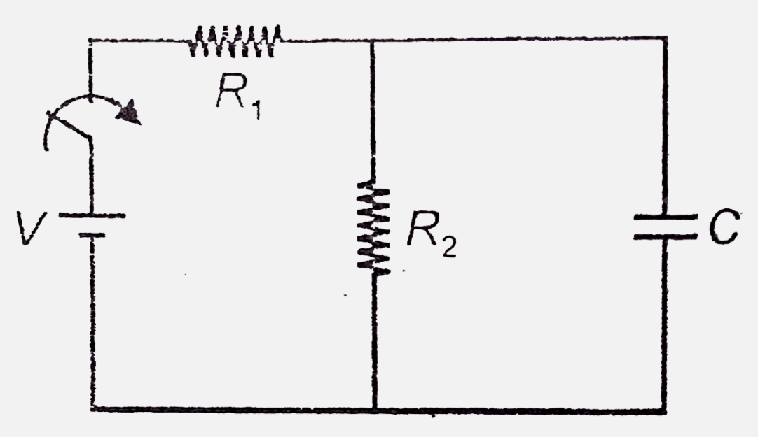
View SolutionConsider the circuit shown. Switch is closed at t=0. Find the current through the battery as a function of time. Initially capacitor was uncharged.
View Solution

