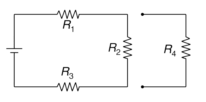
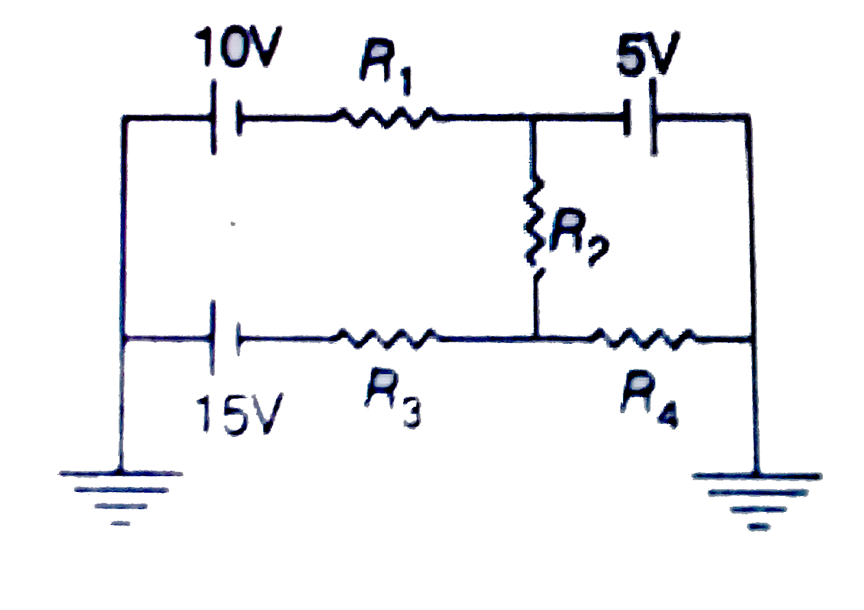
In the circuit shown in the fig., R1:R2:R3=4:1:2.
(a) Will the current through R1 increase or decrease when a new resistance R4 is added in parallel to R2 ?
(b) Change in current through R1 when R4 is added is found to be 0.2A. Calculate the current through R4.
The correct Answer is:(a) Increase
(b) I4=1.4A
Step by step video, text & image solution for In the circuit shown in the fig., R_(1): R_(2) : R_(3) = 4 : 1 : 2. (a) Will the current through R_(1) increase or decrease when a new resistance R_(4) is added in parallel to R_(2) ? (b) Change in current through R_(1) when R_(4) is added is found to be 0.2 A. Calculate the current through R_(4). by Physics experts to help you in doubts & scoring excellent marks in Class 12 exams.
Topper's Solved these Questions
Similar Questions
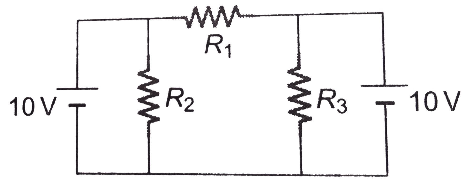
In the curcuit shown in figure R1=R2=R3=10Ω. Find the currents through R1 and R2
 View Solution
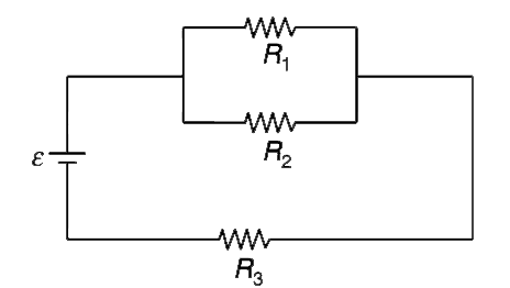
In the circuit shown in the figure R1=3Ω,R2=2ΩandR3=5Ω Emf of the cell ε=6 Volt.
(a) Infinitely many 1Ω resistors are added in parallel to R1andR2. Find current through R2 and potential drop across it.
(b) Infinitely many 1Ω resistors are added in series to R3. Find the potential drop across R3 and current through it.
 View Solution
Knowledge Check
- Question 1 - Select One
In fig the current through resistance (R) is
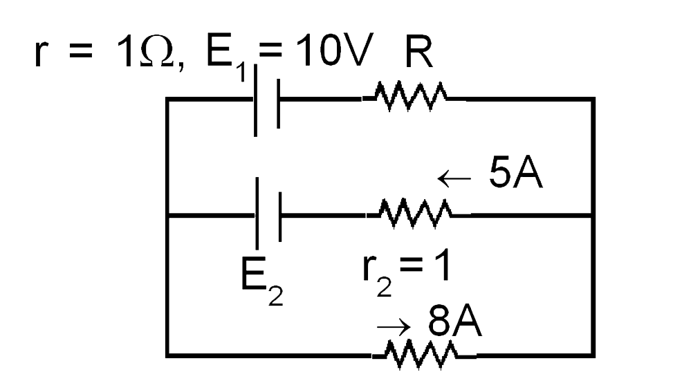 A3AB13AC6.5AD9A
 - Question 2 - Select One
In the circuit shown in figure
For what ratio R2R4, current through R3 will be zeroA1:1B1:2C1:3DNot possible - Question 3 - Select One
In the circuit shown, E1=7V,E2=7V,R1=R2=1Ω and R3=3Ω respectively. The current through the resistance R3
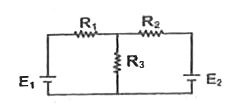 A0.083333333333333B3.5 AC1.75 ADnone of these
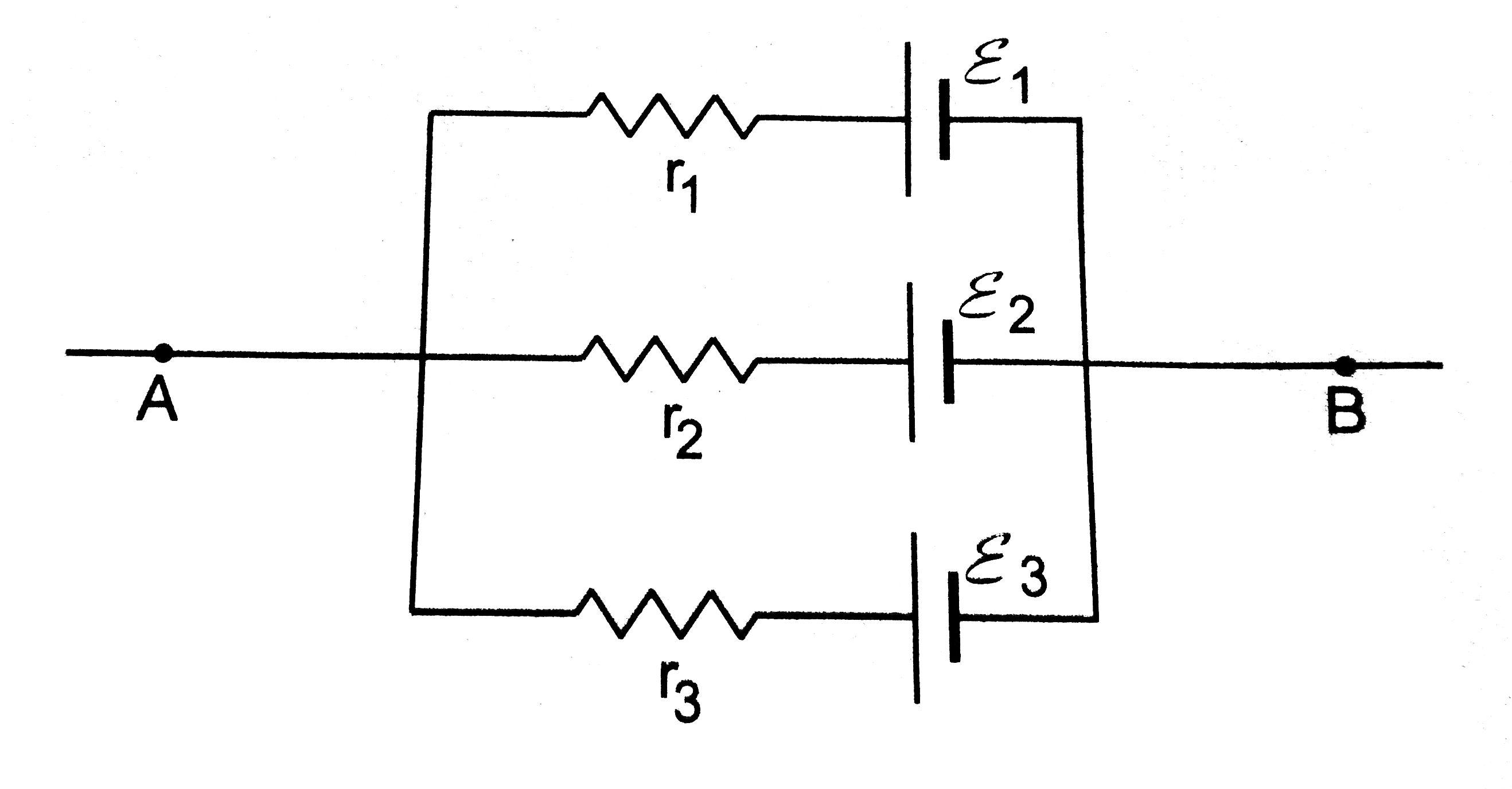
In the circuit shown in figure ,(ε)1=3V,(ε)2=2V,(ε)3=1Vandr1=r2=r3=1(Ω).Find the potential difference between the points A and B and the current through each branch.
 View Solution
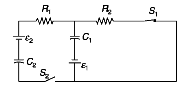
In the circuit shown in the figure R1=R2=5Ω,C1=C2=2μfandε1=ε2=5V. Switch S1 is kept closed for a long time. Now switch S2 is also closed. Immediately after S1 is closed, find
(a) current through R1
(b) current through R2
 View Solution
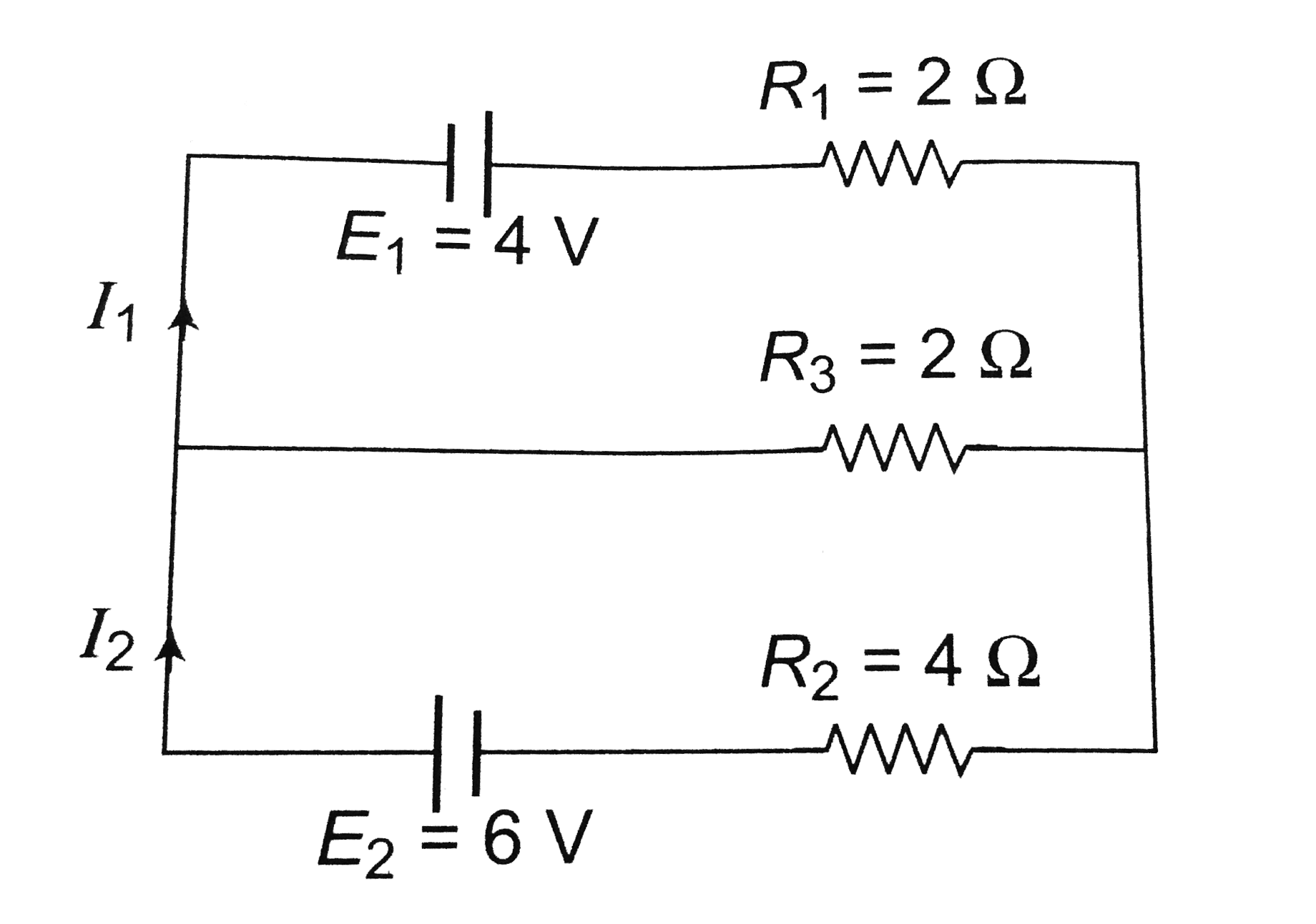
In the circuit shown below E1=4.0V,R1=2Ω,E2=6.0V,R2=4Ω and R3=2Ω. The current I1 is
 View Solution
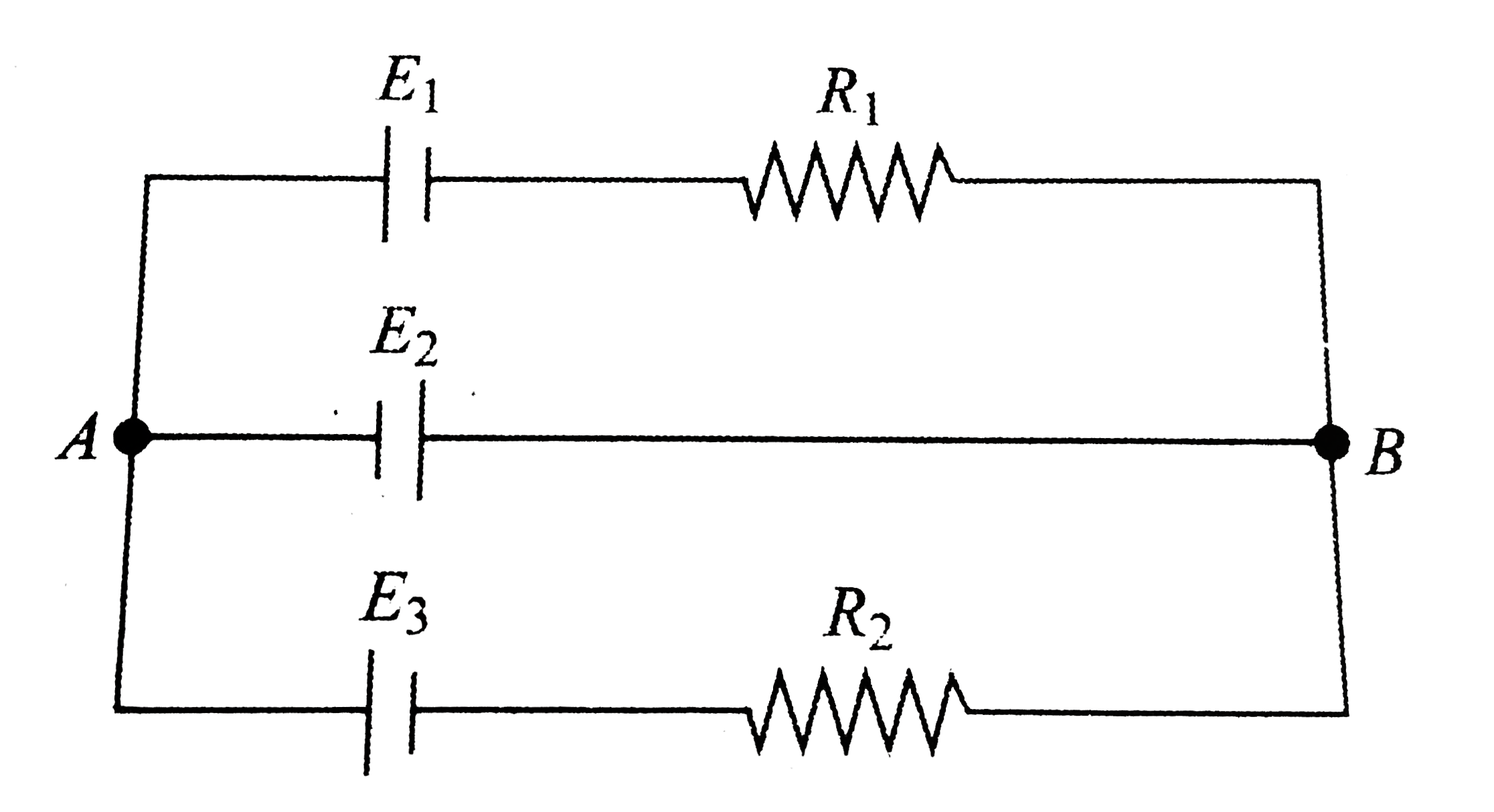
In the circuit shown in fig. 5.265, E1=E2=E3=2V and R1=R2=4Ω. The current flowing between points A and B through battery E2 is
 View Solution
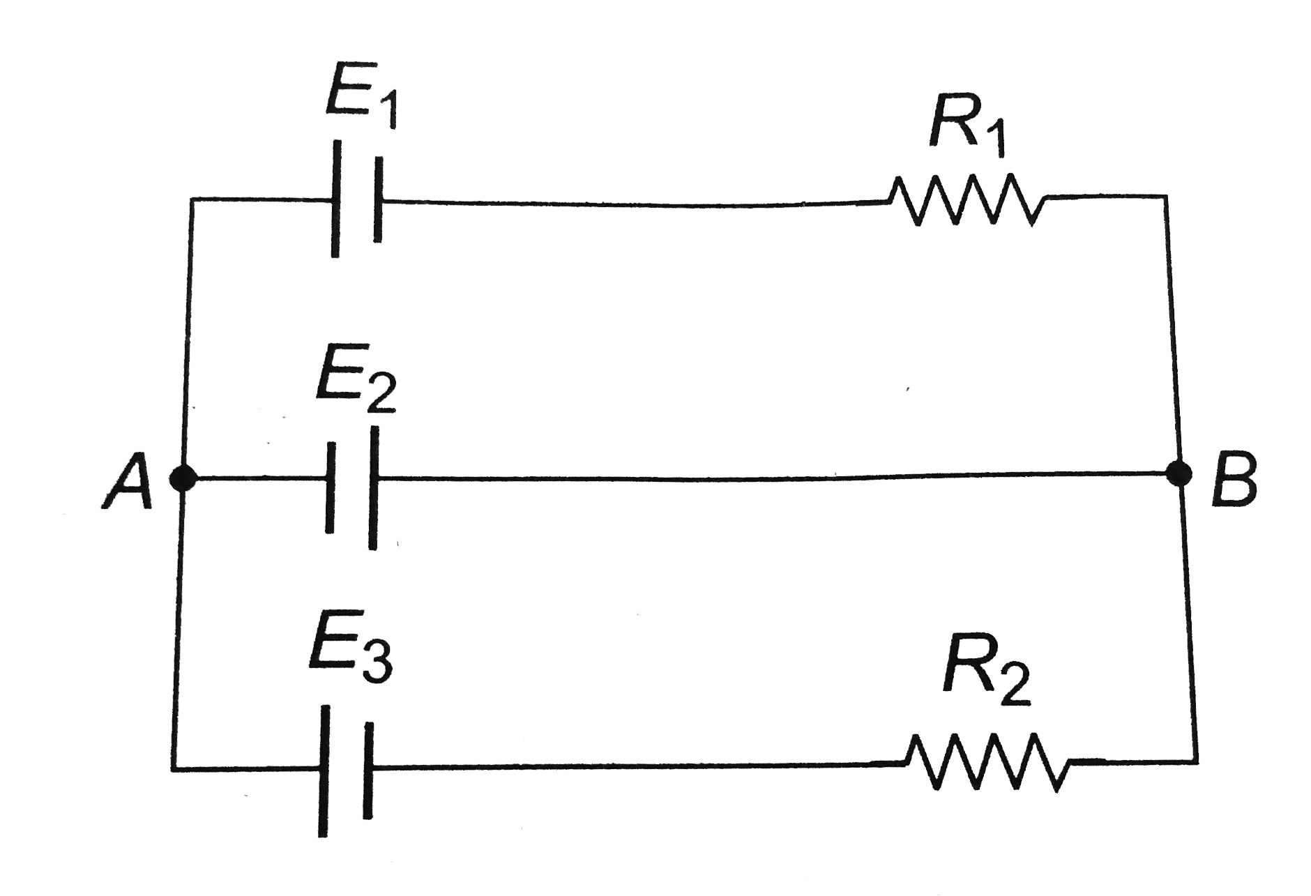
In the circuit shown here, E1=E2=E3=2V and R1=R2=4ohms. The current flowing between point A and B through battery E2 is
 View Solution

