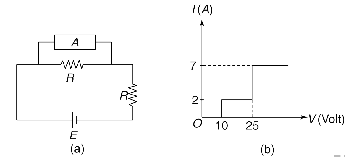
In the circuit shown in figure (a), the emf of the ideal cell is E=100V and resistance R is 10Ω. The current (I) – Voltage (V) characteristic of the circuit contained in box A is as shown in figure (b). find the potential difference across the box A.
Text Solution
The correct Answer is:25 V
|
Topper's Solved these Questions
Similar Questions
Knowledge Check
In the L-R circuit as shown in figure, potential difference across the resistance at some instant is 4 V. Then
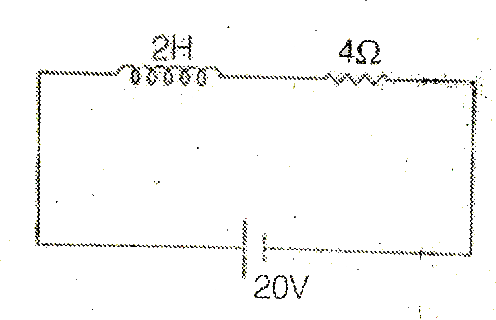 Acurrent is increasing at a rate of 8A/s at this instantBpower supplied by the battery at this instant is 20WCpower stored in the magnetic field at this instant is 16WDcurrent in the circuit at this instant is 1A
In the circuit shown in fig. the cell is ideal with emf 15V. Each resistance is of 3Ω. The potential difference across the capacitoro in steady state is
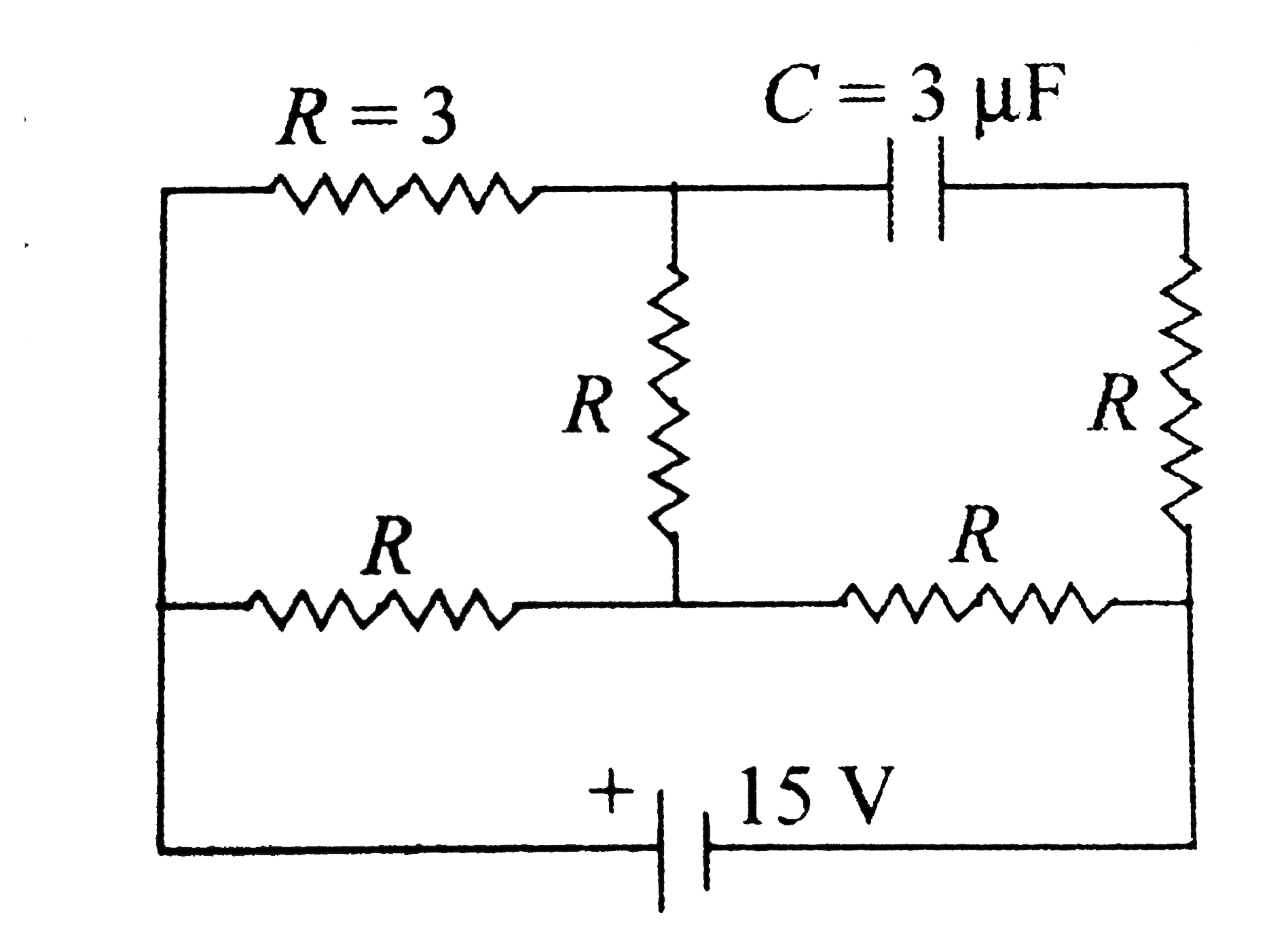 A0B9 VC12 VD15 V
In the circuit shown, the cell is ideal , with emf=15V. Ecah resistance is of 3Ω. the potential difference across the capacitor is
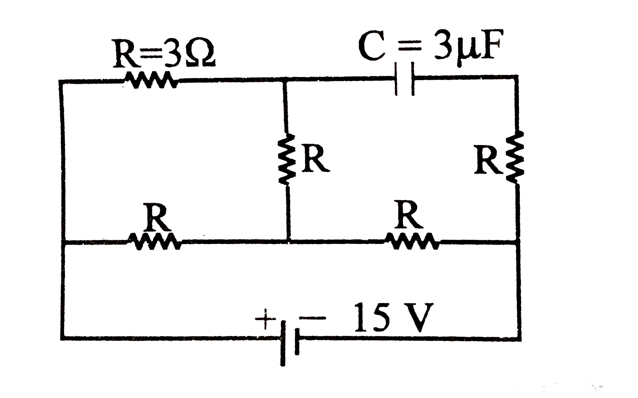 AzeroB9VC12VD15V
A circuit containing five resistors is connected to a battery with a 12 v emf as shown in figure. The potential difference across 4Ω resistor is

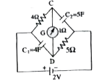
View SolutionIn the circuit shown in Fig., the cell is ideal with e.m.f = 2V. The resistance of the coil of the galvanometer G is 1Ω. Then
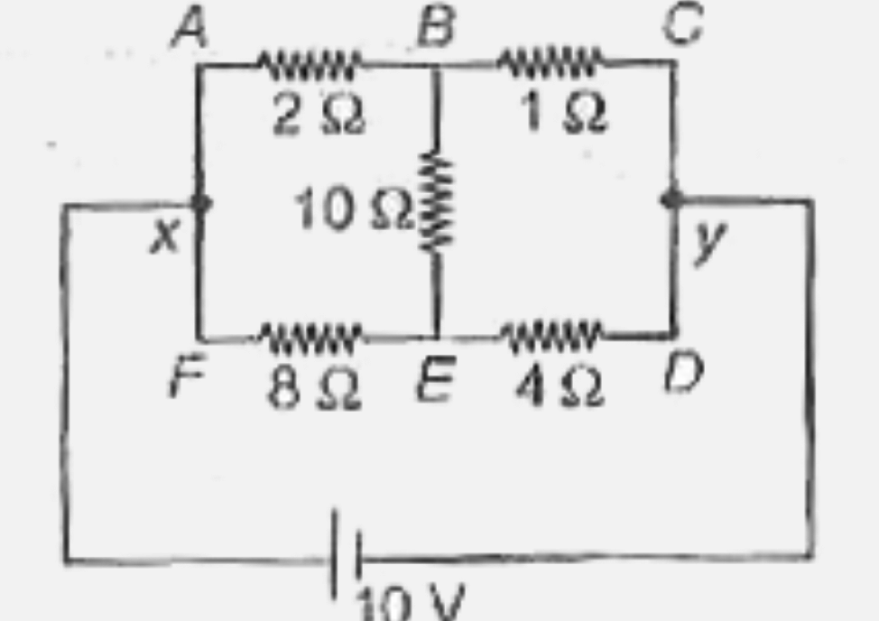
View SolutionA combination of five resistors are connected to a cell of emf 10 V as shown in figure. The potential difference VB−VE will be .
View SolutionIn the circuit diagram shown in figure, potential difference across 3Ω resistance is 20 V. Then, match the following two columns.
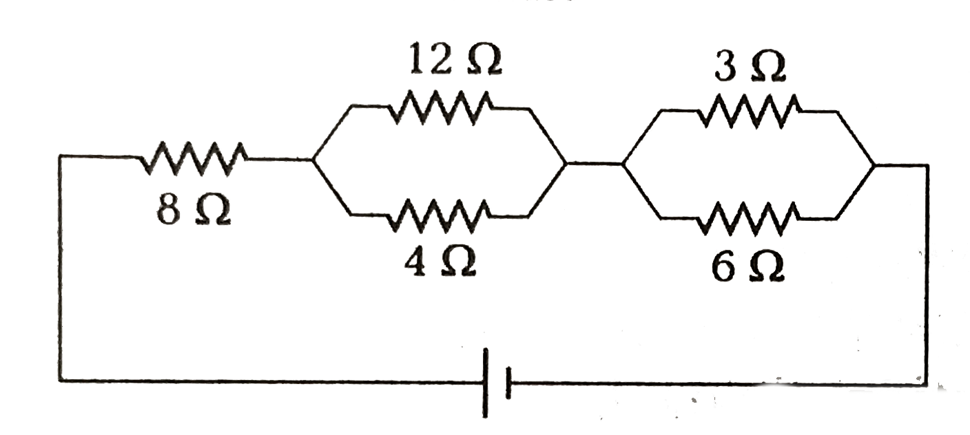
View SolutionIn the circuit diagram shown in figure, potential difference across 3Ω resistance is 20 V. Then, match the following two columns.

View Solution
