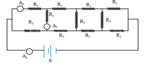
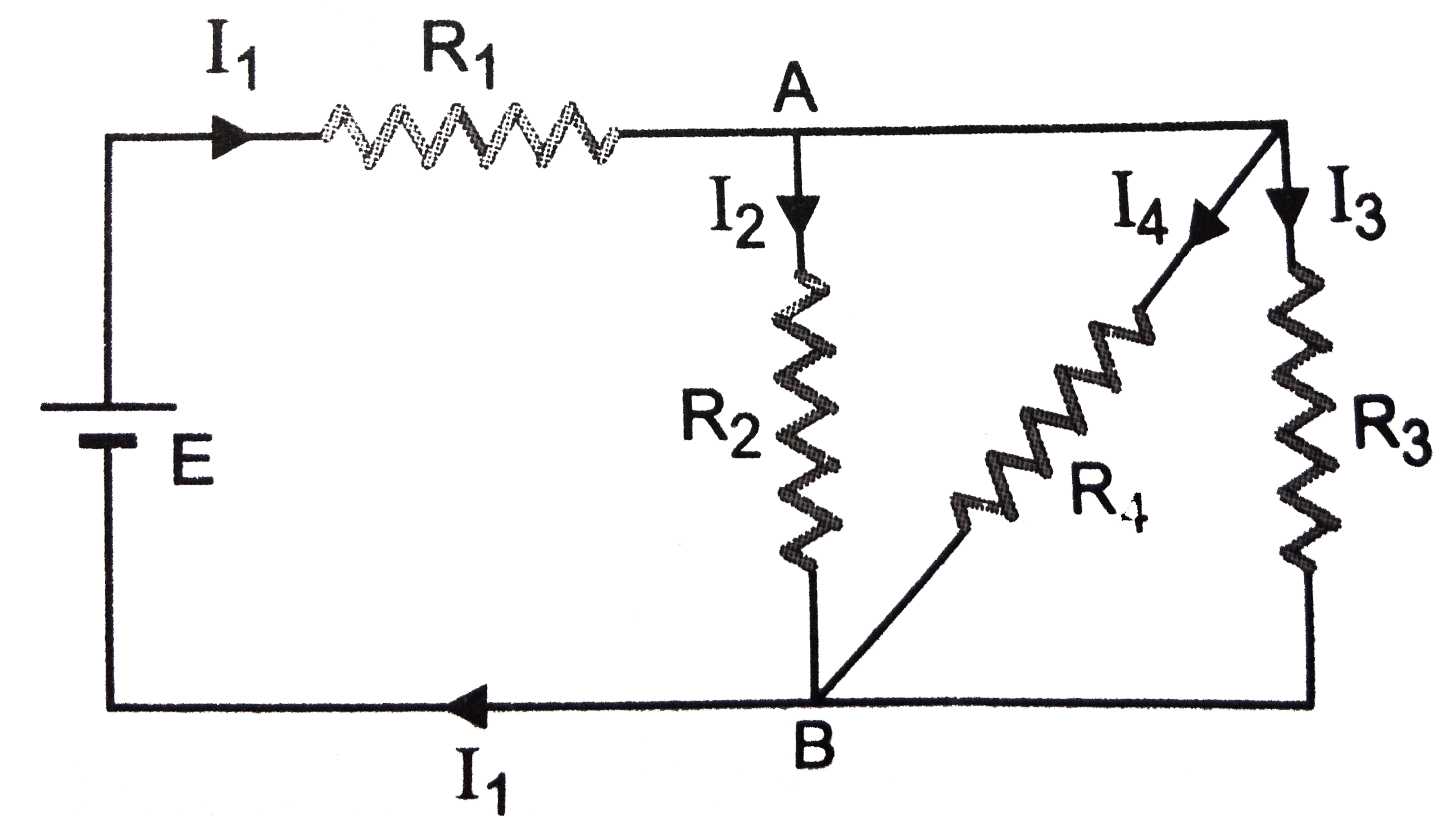
Observe the given circuit.
R1andR2 are two resistors and R1=R2=4Ω. Emf of the battery E is 10 V.
Answer the following questions.
What is the potential difference of the circuit ?

The potential difference across R_(1) is 'E' volts = 10 V.
Topper's Solved these Questions
- ELECTRIC CURRENTBOOK - VGS PUBLICATION-BRILLIANTCHAPTER - ELECTRIC CURRENTEXERCISE - INFORMATION SKILLS AND PROJECTS
19 Videos
- CHEMICAL REACTIONS AND EQUATIONSBOOK - VGS PUBLICATION-BRILLIANTCHAPTER - CHEMICAL REACTIONS AND EQUATIONSEXERCISE - ESSENTIAL MATERIAL FOR EXAMINATION PURPOSE
1 Videos
- ELECTROMAGNETISMBOOK - VGS PUBLICATION-BRILLIANTCHAPTER - ELECTROMAGNETISMEXERCISE - CREATIVE QUESTION FOR NEW MODEL EXAMINATION (SEC-4)
30 Videos
Similar Questions
In the given circuit, R1 = 10Ω R2=6Ω and E = 10V, then correct statement is
View SolutionThe emf and resistances in the circuit of Fig 27-8a have the following values:
ε1=4.4V.ε2=2.1V,
r1=2.3Ω,r2=1.8Ω,R=5.5Ω
(a) What is the current I in the circuit?
(b) What is the potential difference between the terminals of battery 1 in Fig. 27 8a?
View Solution
Knowledge Check
In the given circuit, R1 = 10Ω R2=6Omega and E = 10V, then correct statement is
 AEffective resistance of the circuit is 10ΩBR Reading of A1 is 1//2 amp.CReading of A2 is 1//2 ampDReading of A3 is 1//8 amp.
Internal resistance of battery of emf 2E is R1 and battery of emf E is R2. If the potential difference across the cell of emf 2E is zero, then value of R is
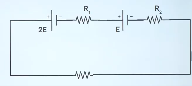 AR1+R22B(R1−R2)CR1−R22DR1−2R22
In Fig, E=5 volt , r=1Ω,R2=4Ω,R1=R3=1Ω and C=3μF. Then the numbercal value of the charge on each plate of the capacitor is
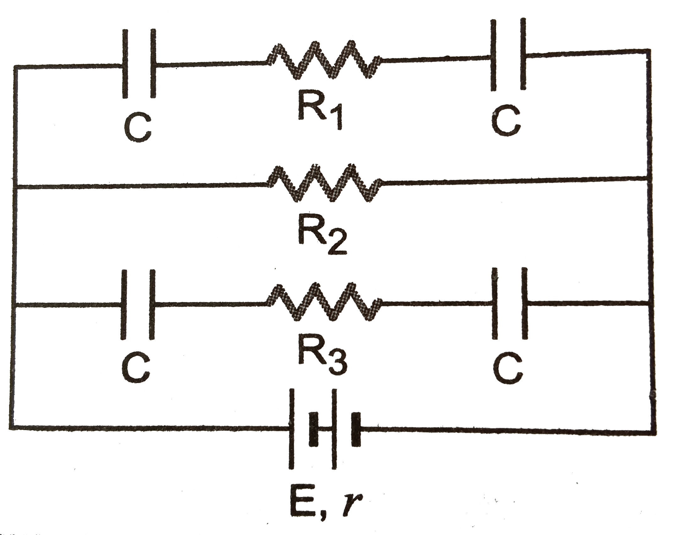 A24μCB12μCC6μCD3μC
If in the figure R1=10Ω,R2=40Ω,R3=30Ω,R4=20Ω,R5=60Ω and a 12 V battery is connected to the arrangement, calculate (i) the total resistance in the circuit and (ii) the total current flowing in the circuit.
View SolutionIn the given network of ideal cells and resistors, R1=1.0Ω,R2=2.0Ω,E1=2V and E2=E3=4V. The potential difference between the point a and b is
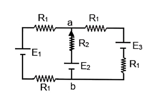
View SolutionIn the circuit R1=4Ω,R2=R3=15ΩR4=30ΩandE=10V Calculate the equivalent resistance of the circuit and current in each resistor
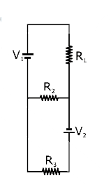
View SolutionTwo ideal batteries of emf V1andV2 and these resistances R1,R2andR3 are connected as shown in the figure . The current in resistance R2 would be zero if
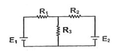
View SolutionIn the circuit shown, E1=7V,E2=7V,R1=R2=1Ω and R3=3Ω respectively. The current through the resistance R3
View Solution
