A pair of parallel conducting rails lie at right angle to a uniform magnetic field of 2.0T as shown in the fig. two resistor 10Ω and 5Ω are to slide without friction along the rail. The distance between the conducting rails is 0.1m. Then
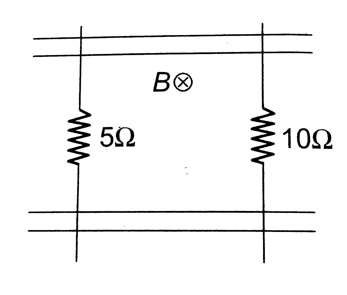
Induced current =1150A directed clockwise if 10Ω resistor is pulled to the right with speed 0.5 ms and 5Ω resistor is held fixed
Induced current =1300A directed anti-clockwise if 10Ω resistor is pulled to the right with speed 0.5ms–1 and 5Ω resistor is held fixed
Induced current =1300A directed clockwise if 5Ω resistor is pulled to the left at 0.5ms−1 and 10Ω resistor is held at rest
Induced current =1150A directed anti-clockwise if 5Ω resistor is pulled to the left at 0.5ms−1 and 10Ω resistor is held at rest
The correct Answer is:D
Step by step video, text & image solution for A pair of parallel conducting rails lie at right angle to a uniform magnetic field of 2.0T as shown in the fig. two resistor 10Omega and 5Omega are to slide without friction along the rail. The distance between the conducting rails is 0.1m. Then by Physics experts to help you in doubts & scoring excellent marks in Class 12 exams.
Updated on:21/07/2023Topper's Solved these Questions
- ELECTRO MAGNETIC INDUCTIONBOOK - ERRORLESS CHAPTER - ELECTRO MAGNETIC INDUCTIONEXERCISE - Assertion & Reason
5 Videos
- CURRENT ELECTRICITYBOOK - ERRORLESS CHAPTER - CURRENT ELECTRICITYEXERCISE - Self Evaluation Test -19
23 Videos
- ELECTRON, PHOTON, PHOTOELECTRIC EFFECT AND X-RAYSBOOK - ERRORLESS CHAPTER - ELECTRON, PHOTON, PHOTOELECTRIC EFFECT AND X-RAYSEXERCISE - Self Evaluation Test
3 Videos
Similar Questions
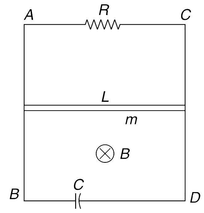
Two long fixed parallel vertical conducting rails AB and CD are separated by a distance L. They are connected by resistance R and a capacitance C at two ends as shown in the figure. There is a uniform magnetic field B directed horizon- tally into the plane of the figure. A horizontal metallic bar of length L and mass m can slide without friction along the rails. The bar is released from rest at t = 0. Neglect resistance of bar and rails and also neglect the self inductance of the loop.
(a) Find the maximum speed acquired by the bar after it is released.
(b) Find the speed of the bar as a function of time t.
View SolutionA conducting rod of length l slides at constant velocity v on two parallel conducting rails, placed in a uniform and constant magnetic field B perpendicular to the plane of the rails as shown in Fig.3.49. A resistance R is connected between the two ends of the rails.
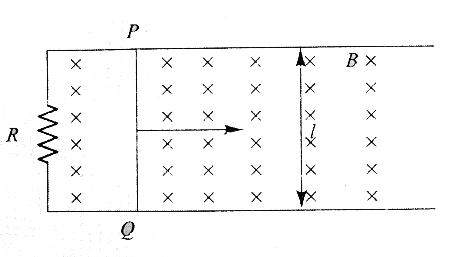
(a) Idenify the cause which produces change in magnetic flux.
(b) Identify the direction of current in the loop.
( c) Determine the emf induced in the loop.
(d) Compute the electric power dissipated in the resistor.
(e) Calcualte the mechenical power required to pull the rod at a cinstant velovity.
View Solution
Knowledge Check
Consider parallel conducting rails separated by a distance l. There exists a uniform magnetic field B perpendicular to the plane of the rails as shown in Fig. Two conducting wires each of length l are placed so as to slide on parallel conducting rails. One of the wires is given a velocity v0 parallel to the rails. Till steady state is achieved, loss in kinetic energy of the system is
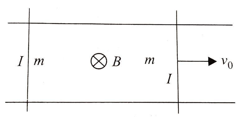 AzeroB3.4mv20C14mv20D38mv20
A conducting rod of length is moved at constant velocity v0 on two parallel, conducting, smooth, fixed rails, that are placed in a uniform constant magnetic field B perpendicular to the plane for the rails as shown in Fig. A resistance R is connected between the two ends of the rails.
Then which of the following is/are correct:
 ATh thermal power dissipated in the resistor is equal to rate of work done by externl person pulling the rod.BIf applied external force is doubled then a part of external power increases the velocity of rod.CLenz's Law is not satisfied if the rod is accelerated by external forceDIf resistance R is doubled then power required to maintain the constant velocity v0 becomes half.
A wire of length l, mass m and resistance R slides without any friction down the parallel conducting rails of negligible resistance . The rails are connected to each other at the bottom by a resistanceless rail parallel to the wire so that the wire and the rails form a closed rectangualr conducting loop. The plane of the rails makes an angle θ with the horizontal and a uniform vertical magnetic field of the inducetion B exists throughout the rregion. Find the steady state velocity of the wire.
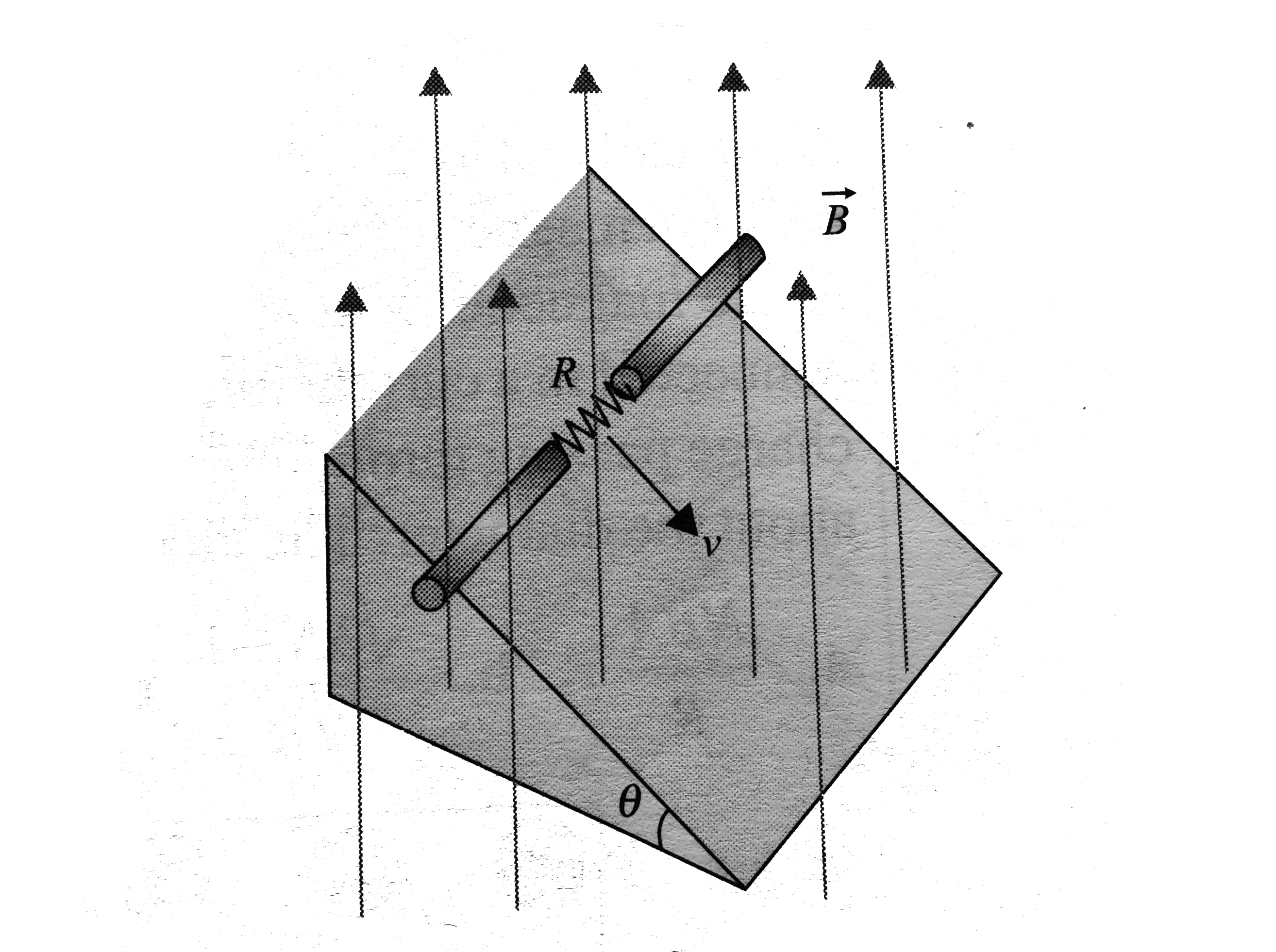 A(a) mgRsinθB2l2cos2θB(b) mgRsin2θB2l2cos2θC( c) mgRsinθB2l2cos2θD( d) mgRsin2θB2l2cosθ
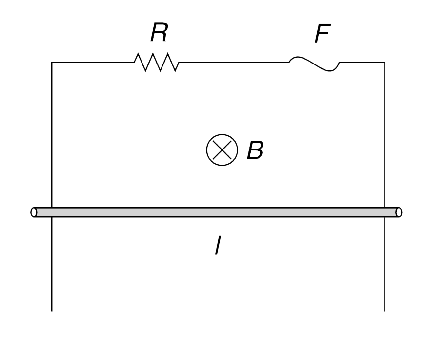
A pair of long conducting rails are held vertical at a separation l=50cm. The top ends are connected by a resistance of R=0.5Ω and a fuse (F) of negligible resistance. A conducting rod is free to slide along the rails under gravity. The whole system is in a uniform horizontal magnetic field B = 1.5 T as shown. Resistance of the rod and rails are negligible and the rod remains horizontal as it moves. The rod is released from rest. Find the minimum mass of the rod that will ensure that the fuse blows out. It is known that rating of the fuse is 4 A.
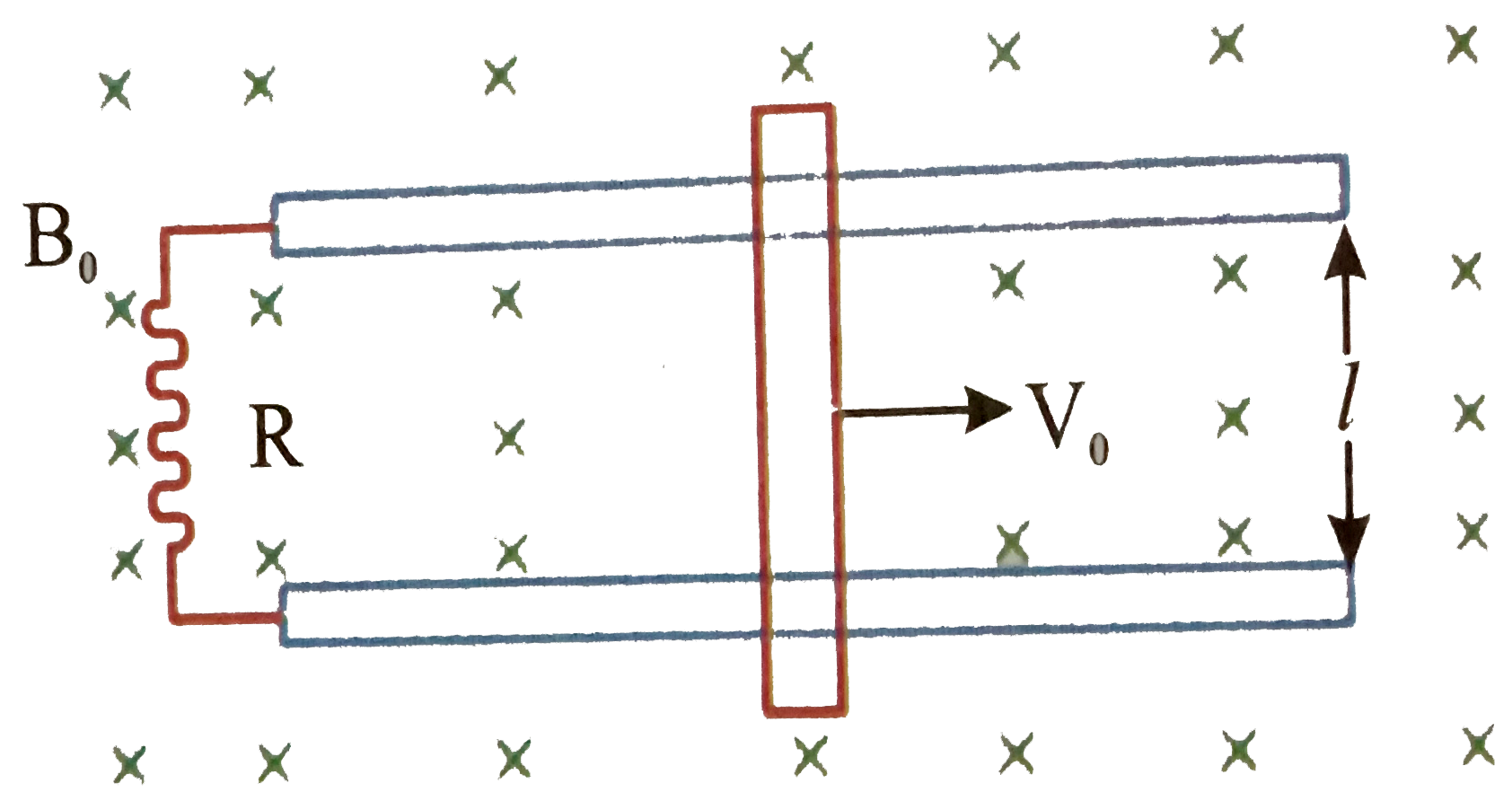
View SolutionA conducting bar mass m and length l moves on two frictionless parallel conducting rails in the presence of a uniform magnetic field B0 directed into the paper. The bar is given an initial velocity v0 to the right and is released at t=0. The velocity of the bar as a function of time is given by
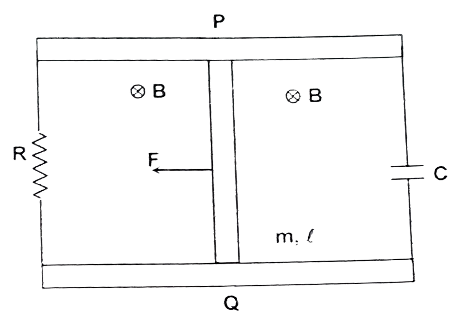
View SolutionTwo smooth horizontal parallel conducting rails are connected with a capacitor and a resistor at the two ends as shown. A uniform conducting rod PQ of mass 'm' and length 'l' is dragged with a constant horizontal force 'F'. The terminal velocity aquired by the conducting rod is
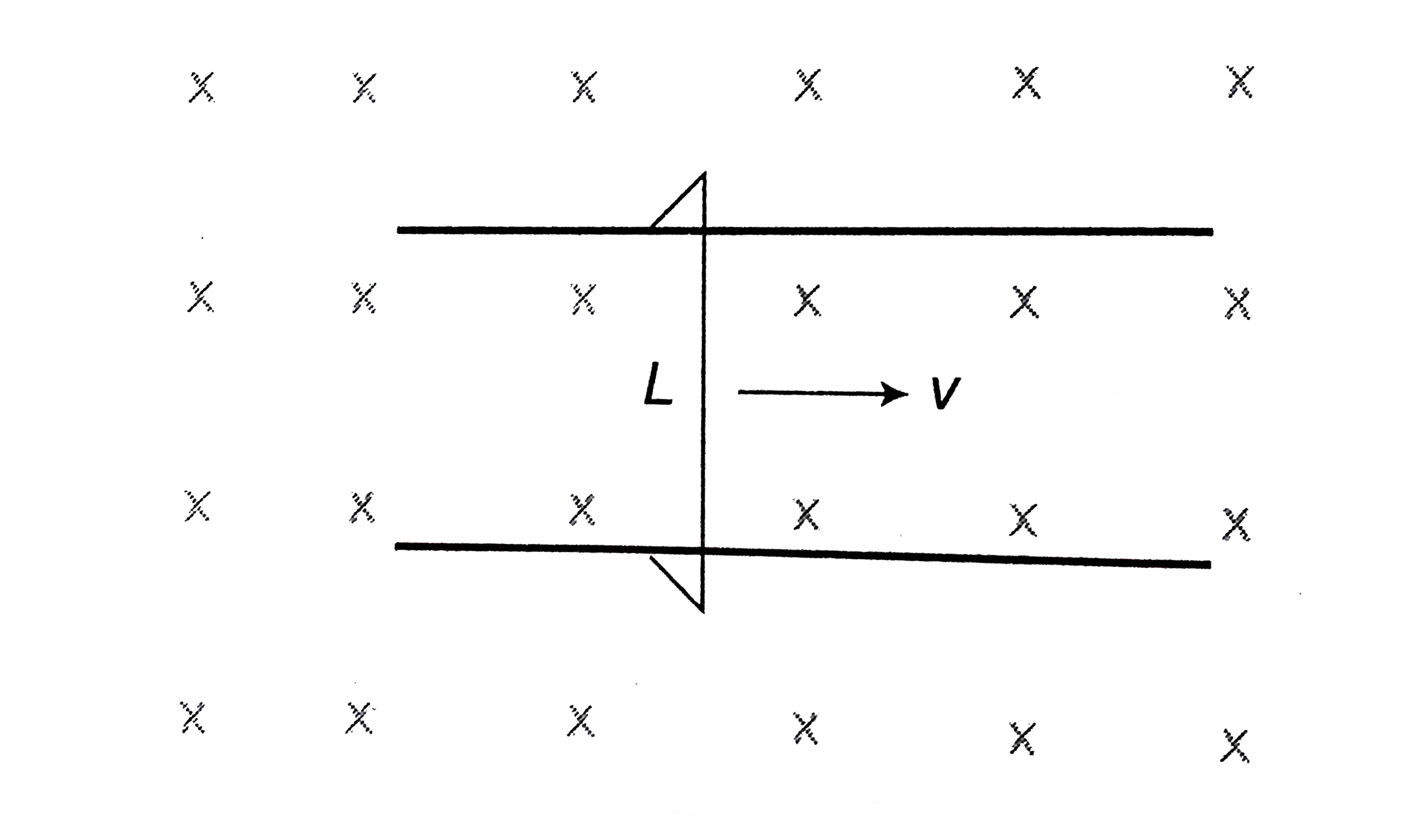
View SolutionFigure shows a wire sliding on two parallel, conducting rails placed at a separation L . A magnetic field B exists in a direction perpendicular to the plane of the rails. What force is necessary to keep the wire moving at a constant velocity V ?
View SolutionTwo long parallel conducting horizontal rails are connected by a conducting wire at one end. A uniform magnetic field B (directed vertically downwards) exists in the region of space.
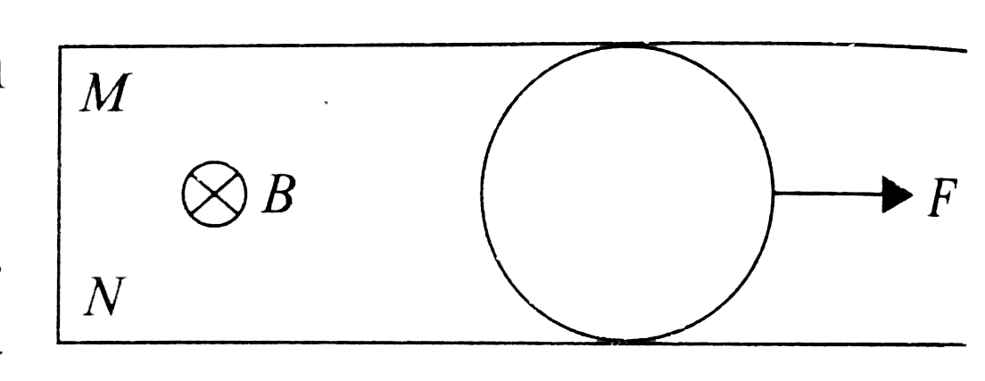
A light uniform ring of diameter d which is practically equal to separation between the rails is placed over the rails as shown in Fig. If resistance of ring be (λ) per unit length
The force required to pull the ring with uniform velocity v is
View Solution
