Two capacitors of capacity 6μF and 3 muFarechar≥100 Vand50 Vseparatelyandco∩ectedasshown∈NowallthethreeswitchesS_(1),S_(2),andS_(3) are closed.
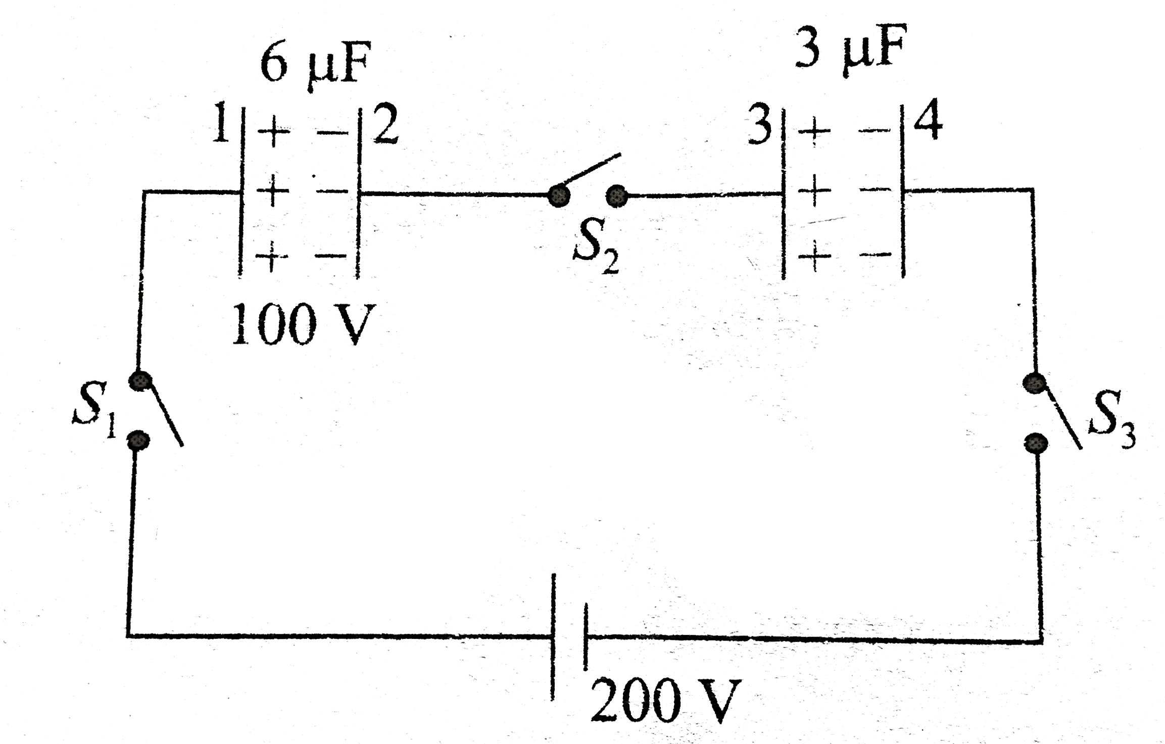
Which plates form an isolated system?
plate 1 and plate 4 separately
plate 2 and plate 3 separately
plates 1 and 4 jointly
plates 2 and 3 jointly
The correct Answer is:D
Step by step video, text & image solution for Two capacitors of capacity 6 muF and 3 muF are charge 100 V and 50 V separately and connected as shown in Now all the three switches S_(1),S_(2), and S_(3) are closed. Which plates form an isolated system? by Physics experts to help you in doubts & scoring excellent marks in Class 11 exams.
Topper's Solved these Questions
- BOOK - DC PANDEYCHAPTER - ELECTROSTATICSEXERCISE - Matrix Matching2videos
ELECTROSTATICS
- BOOK - DC PANDEYCHAPTER - ELECTROSTATICSEXERCISE - Integer17videos
ELECTROSTATICS
- BOOK - DC PANDEYCHAPTER - ELECTROSTATICSEXERCISE - JEE Advanced44videos
ELECTROSTATICS
- BOOK - DC PANDEYCHAPTER - ELASTICITYEXERCISE - Medical entrances s gallery21videos
ELASTICITY
- BOOK - DC PANDEYCHAPTER - EXPERIMENTSEXERCISE - Subjective15videos
EXPERIMENTS
Similar Questions
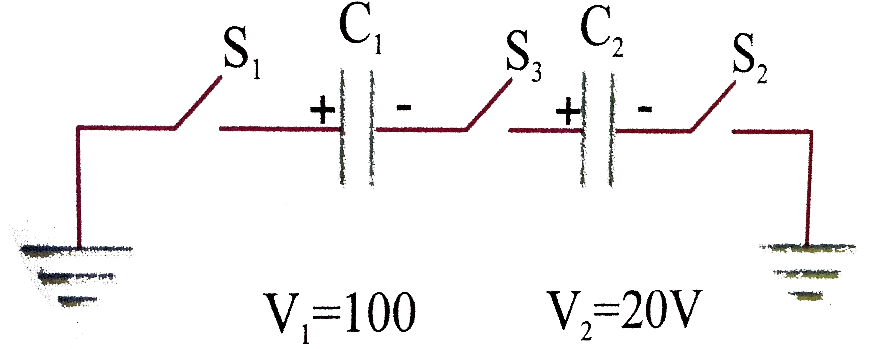
In the circuit shown in figure C1=1μF and C2=2μF. The capacitor C1 is charged to 100V and the capacitor C2 is charged to 20V. After charging then are connected as shown. When the switches S1,S2 and S3 are closed, the charged flowing through S1 is
 .View Solution
Two capacitros of capacity 6μF are charged to 100 V and 50 V separately and connected as shown. Now all the three switches S1,S2 and S3 are closed.

Charges on both the capacitors in steady state will be (on 6μF first)View Solution
Knowledge Check
- Question 1 - Select One
Two capacitors of capacity 6μF and 3μF are charge 100V and 50V separately and connected as shown in Now all the three switches S1,S2, and S3 are closed.
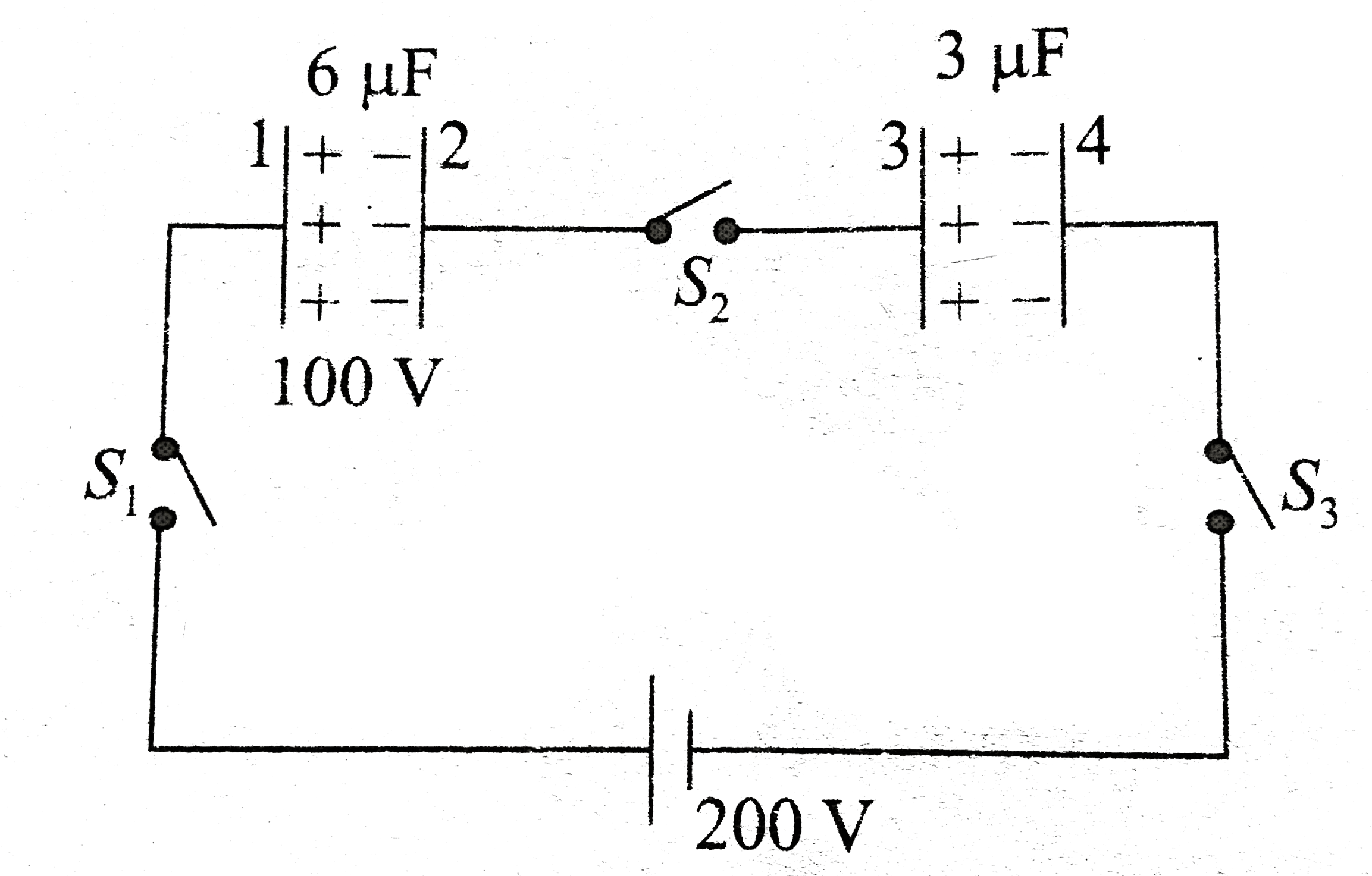
Charge on the 3μF capacitor in steady state willl be.A400μCB700μCC800μCD250μC - Question 2 - Select One
Two capacitors of capacity 6μF and 3μF are charge 100V and 50V separately and connected as shown in (Fig.4.201.) Now all the three switches S1,S2, and S3 are closed.
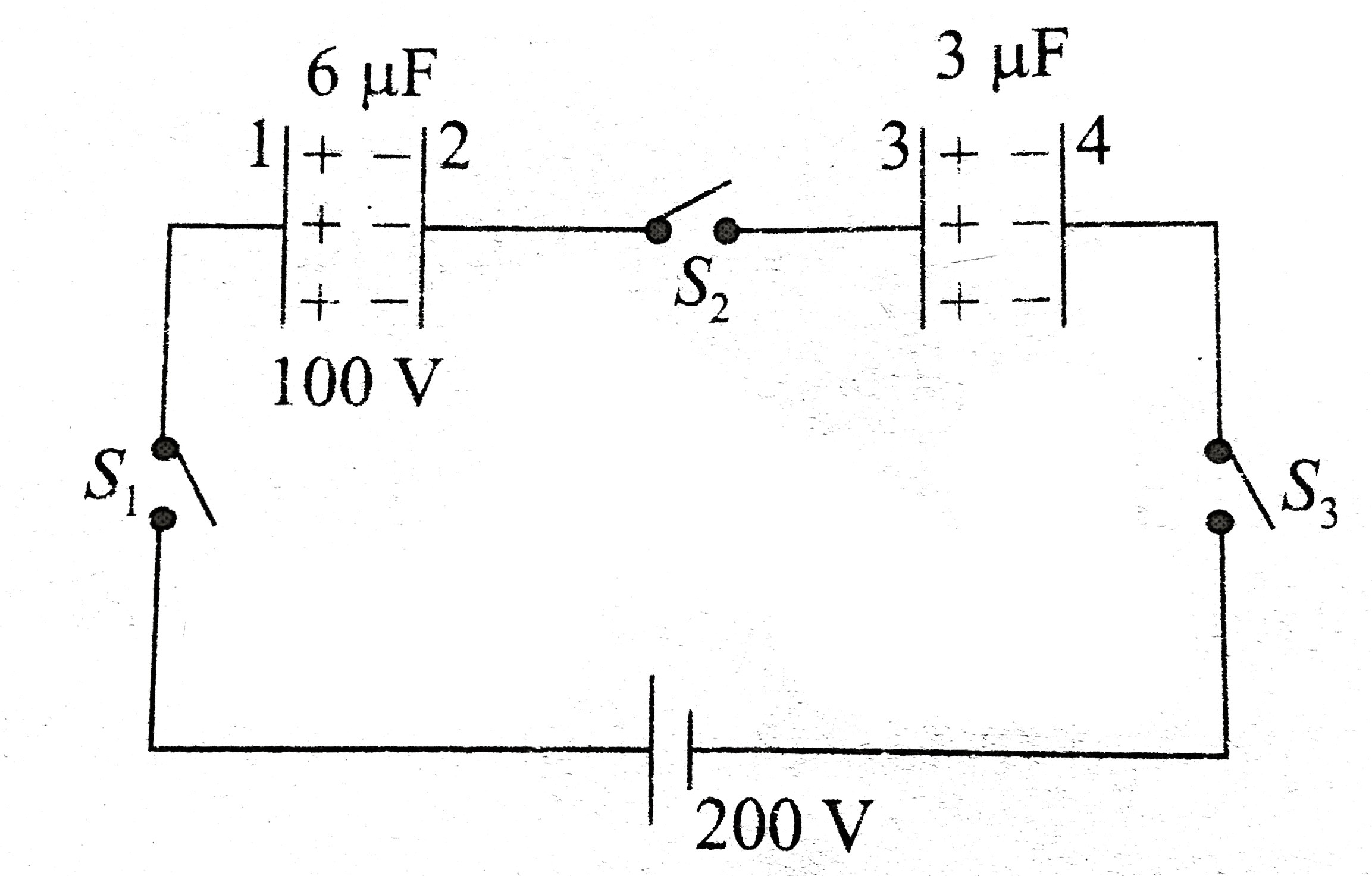
Charge on the 6μF capacitor in steady state will be.A400μCB700μCC800μCD250μC - Question 3 - Select One
Two capacitor of capacity 6μF and 3μF are charged to 100 V and 50 V separately and connected as shown in figure. Now all the three switches S1,S2,andS3 are closed.
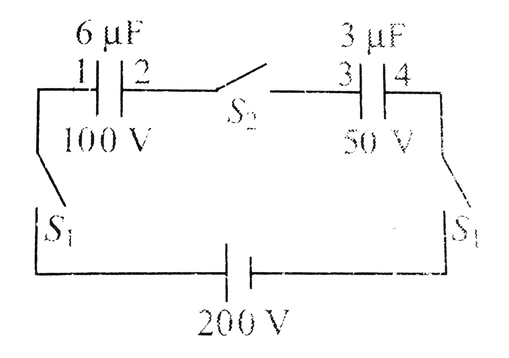
Charges on 6μF And 3μF capacitors in steady state will beA400μC,400μCB700μC,250μCC800μC,350μCD300μC,450μC
Two capacitor of capacity 6μF and 3μF are charged to 100 V and 50 V separately and connected as shown in figure. Now all the three switches S1,S2,andS3 are closed.
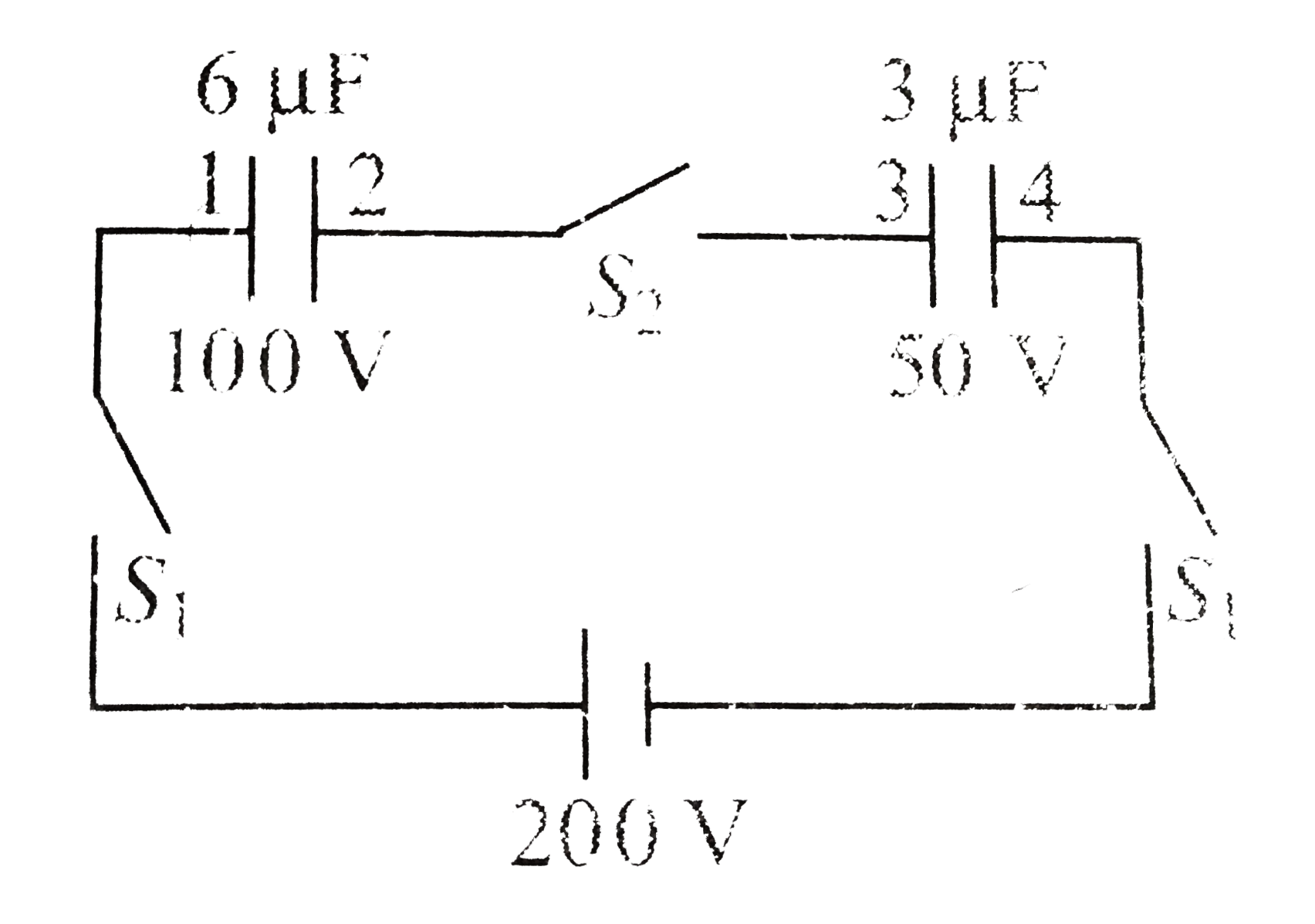
Let q1,q2,andq3 be the magnitudes of charges flown from switches S1,S2,andS3 after they are closed. ThenView SolutionTwo capacitros of capacity 6μF are charged to 100 V and 50 V separately and connected as shown. Now all the three switches S1,S2 and S3 are closed.

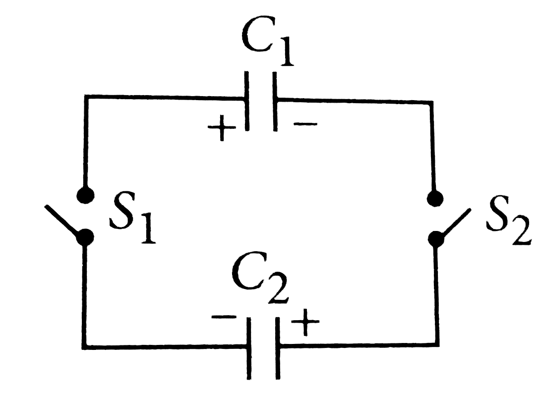
Suppose q1,q2 and q3 be the magnitudes of charge flown from switches S1,S2 and S3 after they closed. ThenView SolutionTwo capacitorsC1=4μFandC2=2μF are charged to same potential V = 500 Volt, but with opposite polarity as shown in the figure. The switches S1andS2are closed.
View SolutionTwo capacitors C1=2μF and C2=1μF are charged to same potential V=100V, but with opposite polarity as shown in the figure.
The switches S1 and S2 are closed. The ratio of final energy to the initial energy of the system is
 View Solution
Two capacitors of capacitance 2μFand5μF are charged to a potential difference 100V and 50 V respectively and connected such that the positive plate of one capacitor is connected to the negative plate of the other capacitor after the switch is closed, the initial current in the circuit is 50 mA. the total resistance of the connecting wires is (in Ohm):
View Solution

