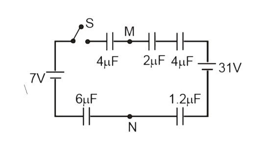
Five capacitors are connected as shown in the figure. Initially S is opened and all capacitors are uncharged. When S is closed, steady state is obtained. Then find out potential difference between the points M and N.
14
12
10
15
The correct Answer is:B
Step by step video & image solution for Five capacitors are connected as shown in the figure. Initially S is opened and all capacitors are uncharged. When S is closed, steady state is obtained. Then find out potential difference between the points M and N. by Physics experts to help you in doubts & scoring excellent marks in Class 12 exams.
Updated on:21/07/2023Topper's Solved these Questions
- Capacitance BOOK - MOTIONCHAPTER - Capacitance EXERCISE - EXERCISE -2
36 Videos
- Capacitance BOOK - MOTIONCHAPTER - Capacitance EXERCISE - EXERCISE -2 LEVEL (II)
22 Videos
- Capacitance BOOK - MOTIONCHAPTER - Capacitance EXERCISE - EXERCISE -4 LEVEL II
19 Videos
- CALORIMETRY BOOK - MOTIONCHAPTER - CALORIMETRY EXERCISE - EXERCISE - 3 Section - B
4 Videos
- CENTRE OF MASSBOOK - MOTIONCHAPTER - CENTRE OF MASSEXERCISE - Exercise - 4 Level-II
20 Videos
Similar Questions
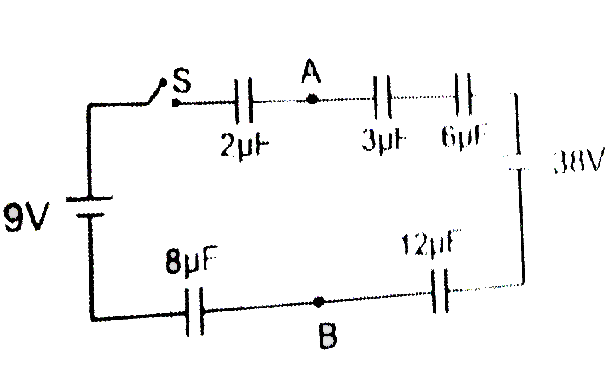
Five capacitors are connected as shown in the figure. Initially S is opened and all the capacitors are uncharged . When S is closed and steady state is obtained. Then find out potential difference between the points A and B in volt.
View SolutionFive capacitors are connected as shown in figure. Find the equivalent capacitance between points A and B.

View Solution
Knowledge Check
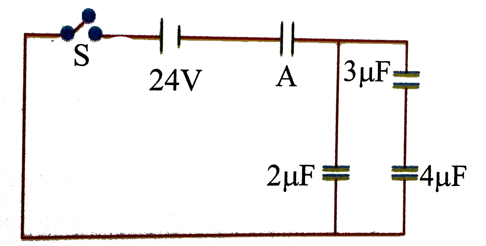
Four capacitor and a battery of emf24V are connected as shown in the figure. Initially, S is open and the capacitors are uncharged. After S is closed and steady state is attained, the potential difference across the 4μf capacitor is 7.5V. The capacitance in μf of the capacitor A is.
 .A5B7C8D10
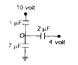
Three capacitors are connected as shown in the figure . The potential at point O is equal to
 A1.4 voltB4.7 voltCZeroD1.8 volt
In the circuit shown in figure potential difference between the points A and B in the steady state is
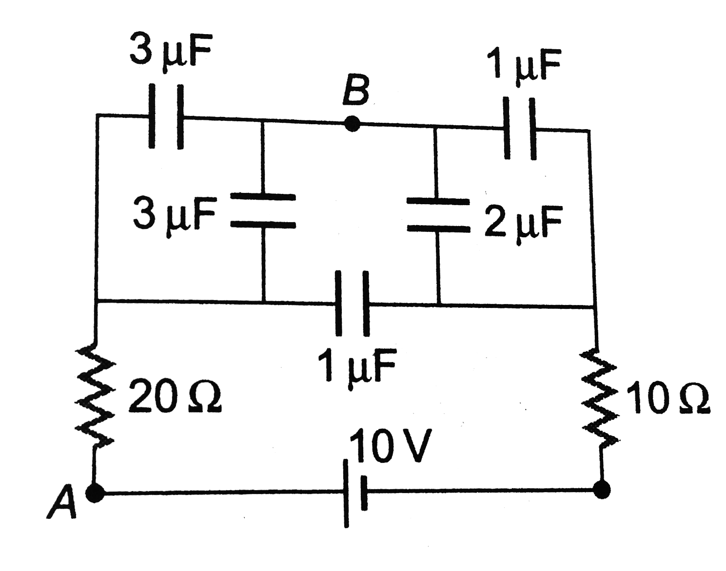 AzeroB6VC4VD103V
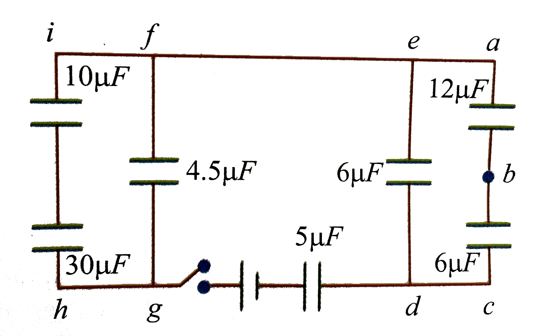
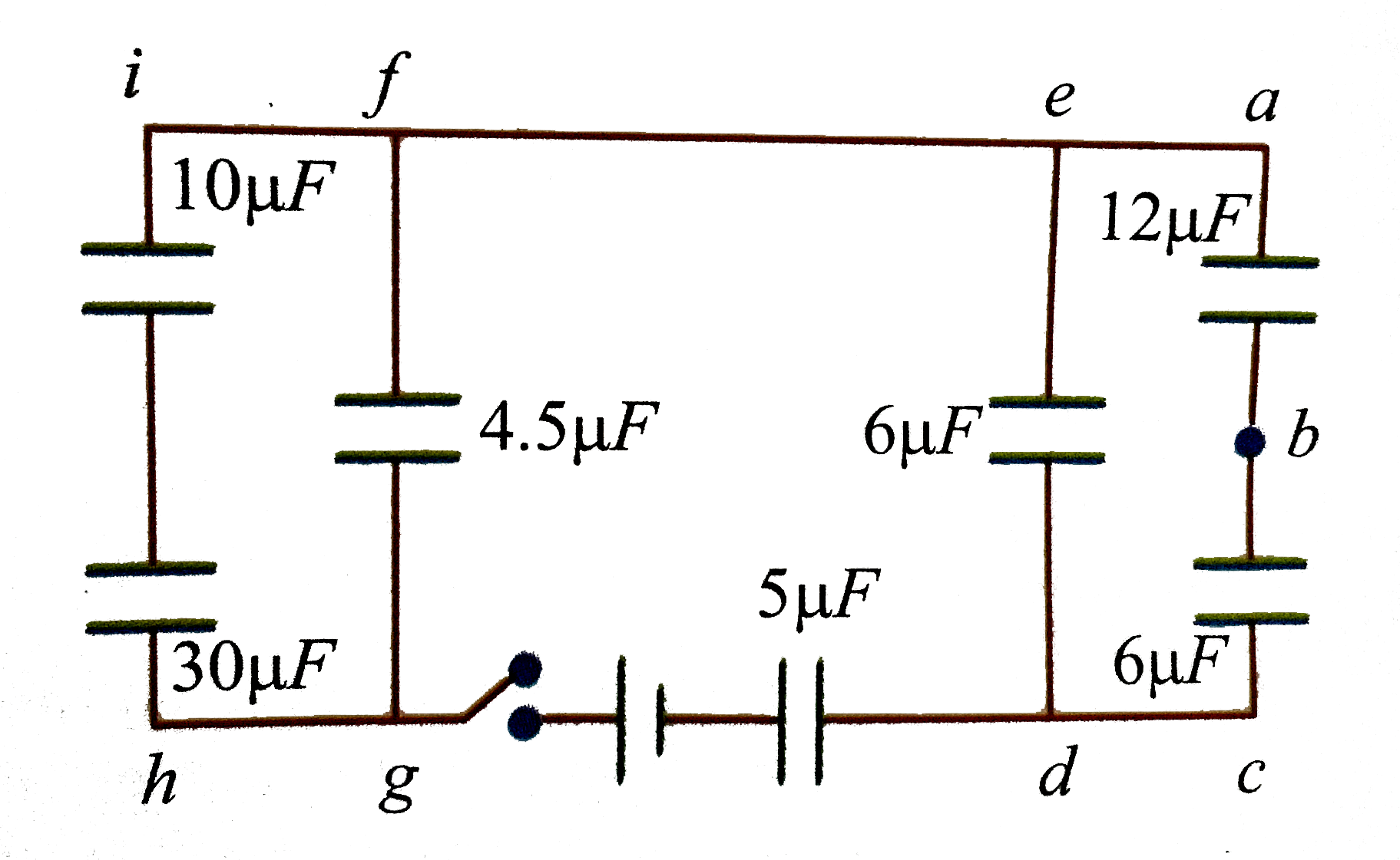
In the circuit diagram shown here seven capacitors are connected to a source of emf E. Initially, the switch S is closed and steady state attained. Now, the potential difference between the points 'a' and 'b' is 4 volt. Now, answer the following :
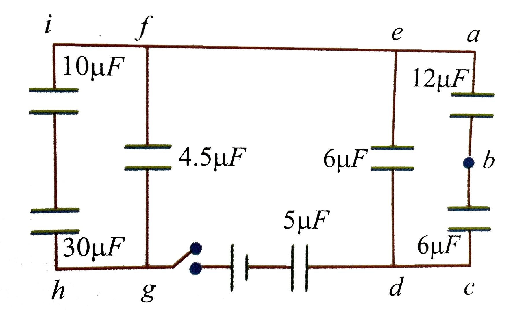 .
.
The emf E of the battery is :
View SolutionIn the circuit diagram shown here seven capacitors are connected to a source of emf E. Initially, the switch S is closed and steady state attained. Now, the potential difference between the points 'a' and 'b' is 4 volt. Now, answer the following :
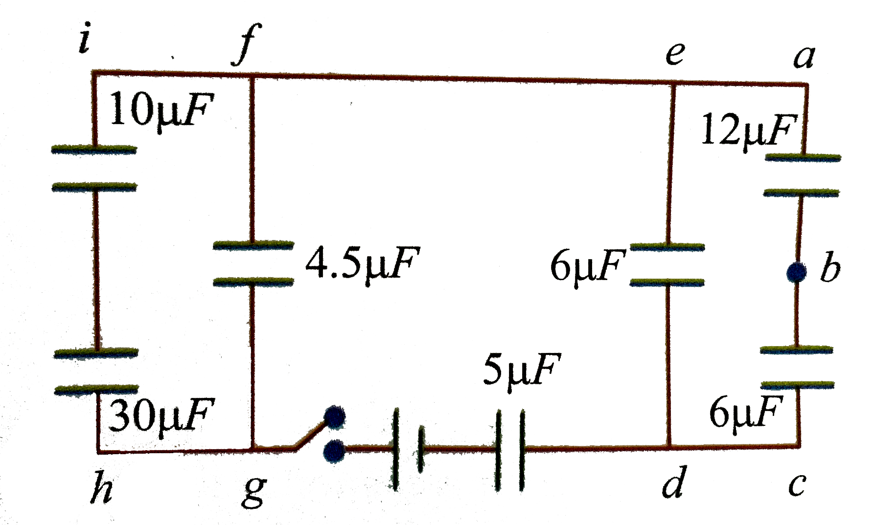 .
.
The charge on 10μF is :
View SolutionIn the circuit diagram shown here seven capacitors are connected to a source of emf E. Initially, the switch S is closed and steady state attained. Now, the potential difference between the points 'a' and 'b' is 4 volt. Now, answer the following :
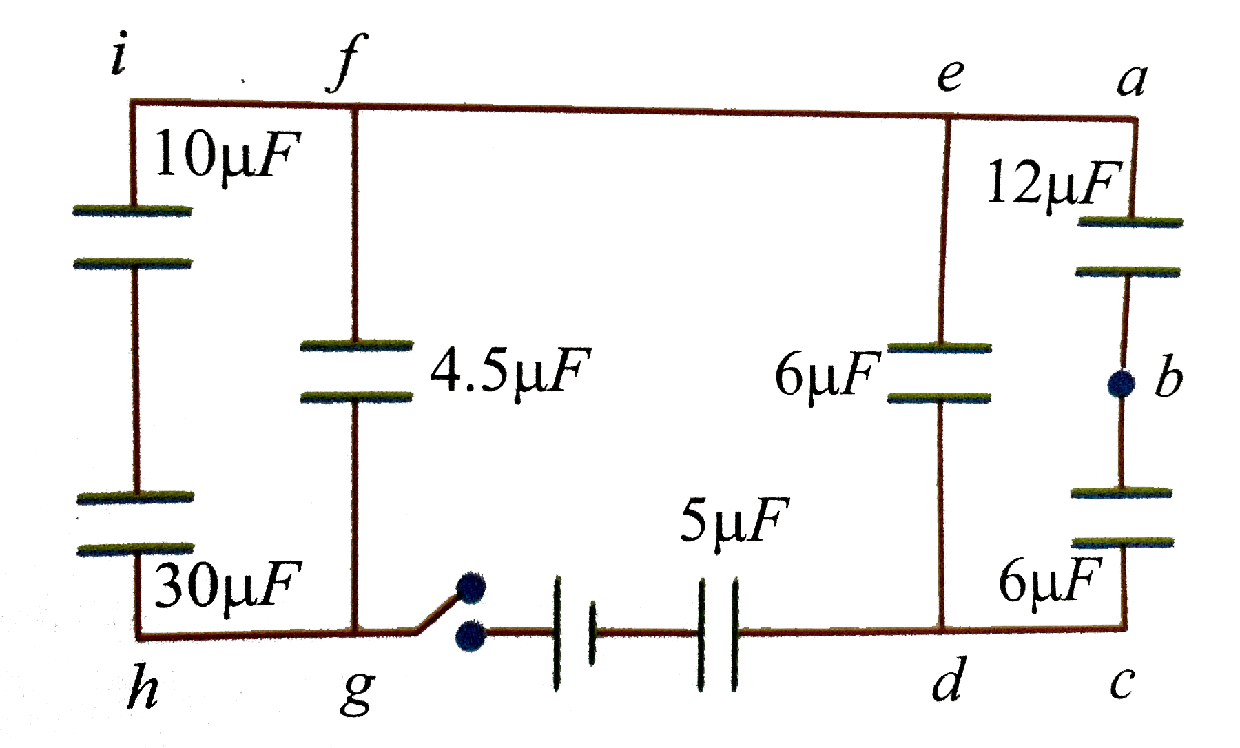 .
.
The charge on 5μC is :
View SolutionIn the circuit diagram shown here seven capacitors are connected to a source of emf E. Initially, the switch S is closed and steady state attained. Now, the potential difference between the points 'a' and 'b' is 4 volt. Now, answer the following :
 .
.
The charge on 4.5μF is :
View SolutionIn the circuit diagram shown here seven capacitors are connected to a source of emf E. Initially, the switch S is closed and steady state attained. Now, the potential difference between the points 'a' and 'b' is 4 volt. Now, answer the following :
 .
.
The charge on 12μF is :
View Solution