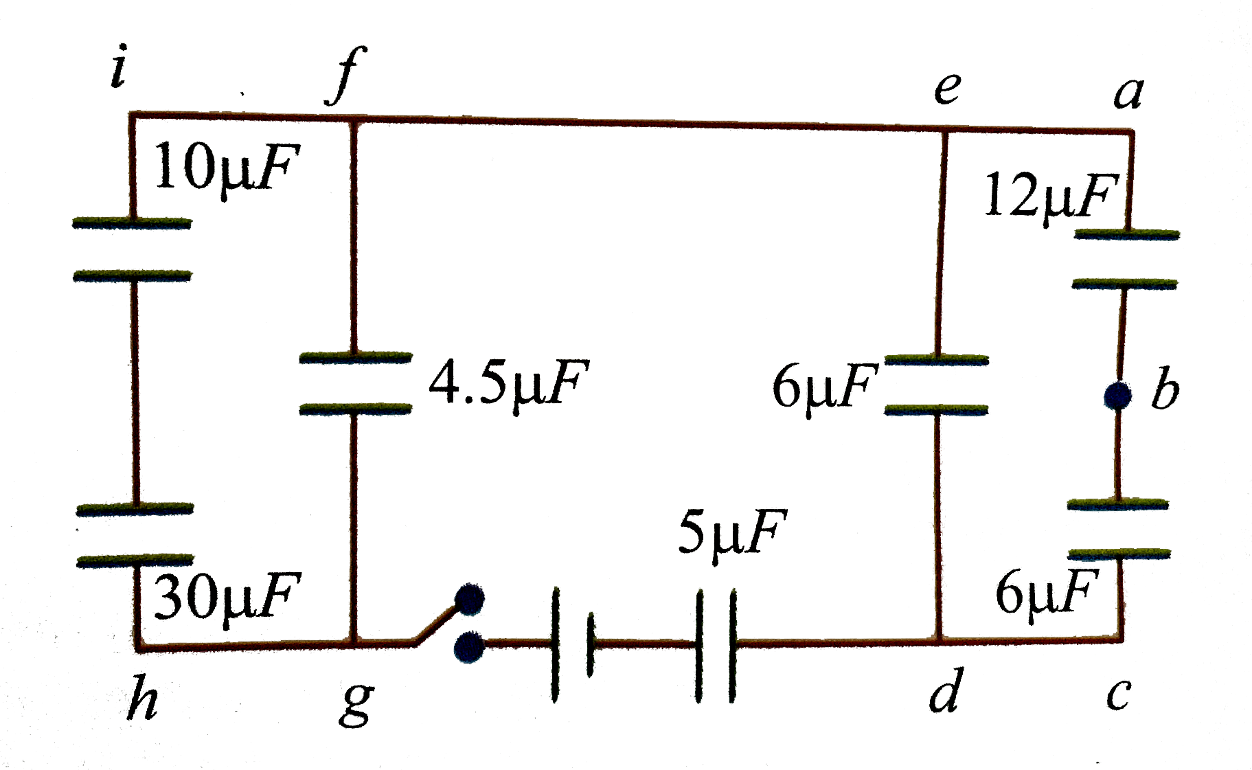
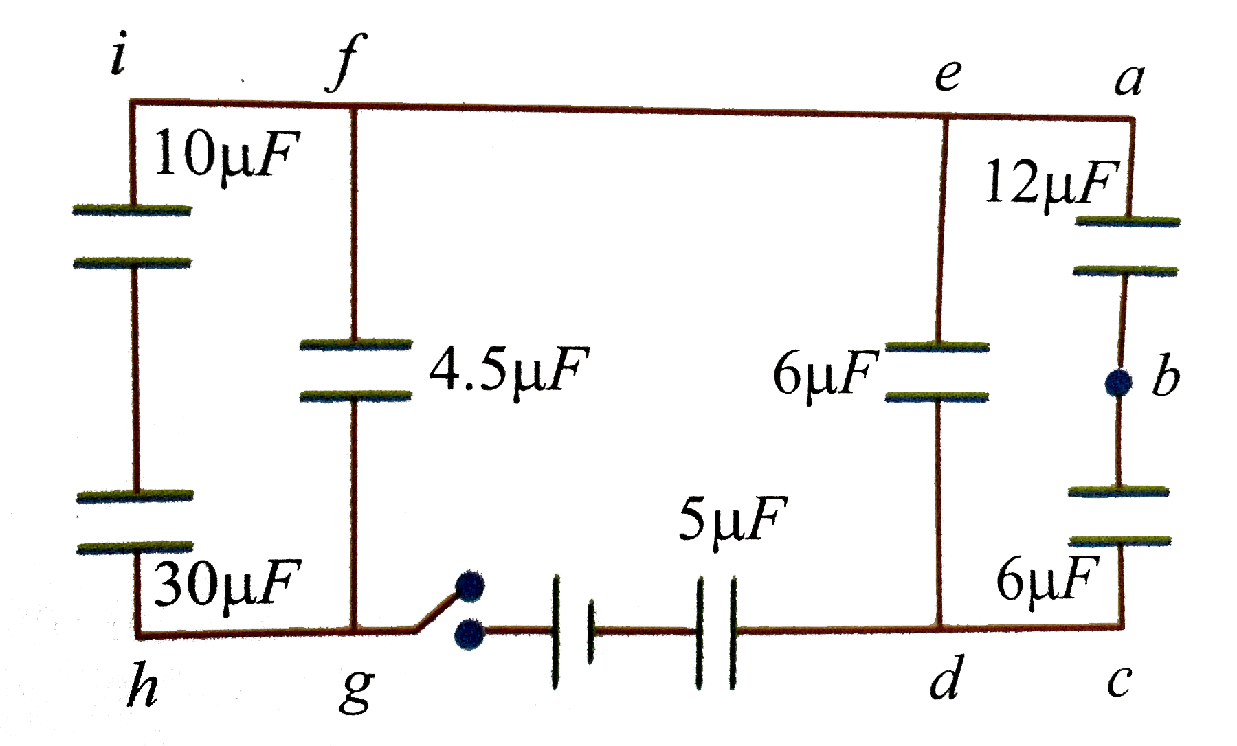
In the circuit diagram shown here seven capacitors are connected to a source of emf E. Initially, the switch S is closed and steady state attained. Now, the potential difference between the points 'a' and 'b' is 4 volt. Now, answer the following :
 .
.
The charge on 12μF is :
48μc
90μc
120μc
60μc
The correct Answer is:A
Ceff=12046μC
Charge supplied by battery (i.e)
C5=120μC
∴E=46VQfg=45μCQ10=75μC.
Topper's Solved these Questions
- BOOK - NARAYNACHAPTER - CAPACITANCEEXERCISE - Subjective9videos
CAPACITANCE
- BOOK - NARAYNACHAPTER - CAPACITANCEEXERCISE - Previous IIT-JEE16videos
CAPACITANCE
- BOOK - NARAYNACHAPTER - CAPACITANCEEXERCISE - Level-V35videos
CAPACITANCE
- BOOK - NARAYNACHAPTER - ATOMS EXERCISE - EXERCISE -447videos
ATOMS
- BOOK - NARAYNACHAPTER - COMMUNICATION SYSTEMEXERCISE - Level-II(H.W)25videos
COMMUNICATION SYSTEM
Similar Questions
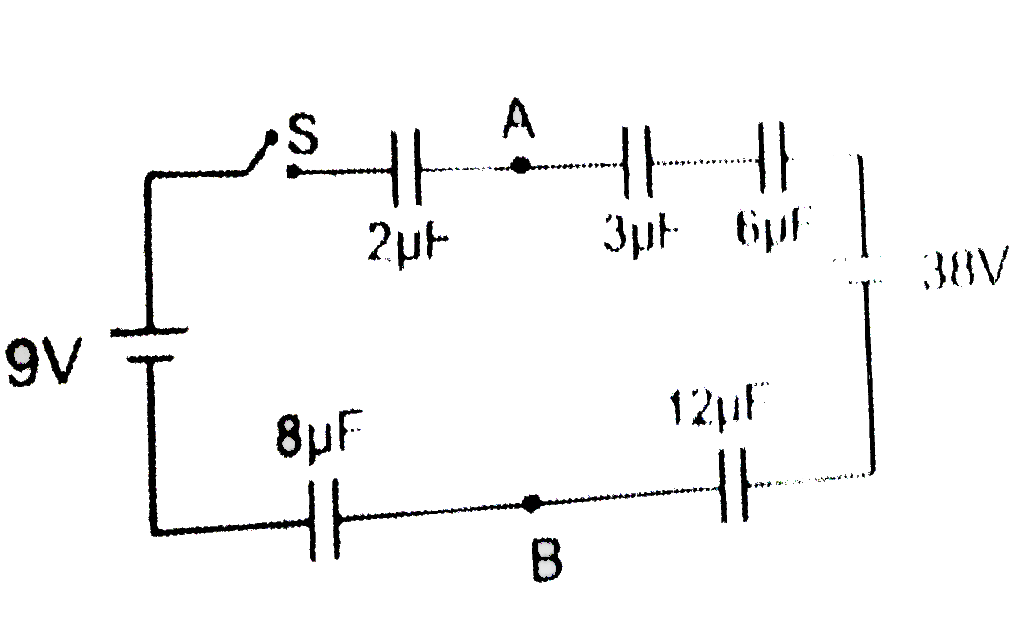
Five capacitors are connected as shown in the figure. Initially S is opened and all the capacitors are uncharged . When S is closed and steady state is obtained. Then find out potential difference between the points A and B in volt.
 View Solution
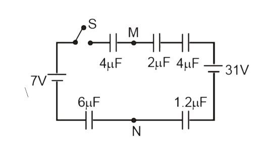
Five capacitors are connected as shown in the figure. Initially S is opened and all capacitors are uncharged. When S is closed, steady state is obtained. Then find out potential difference between the points M and N.
 View Solution
Knowledge Check
- Question 1 - Select One
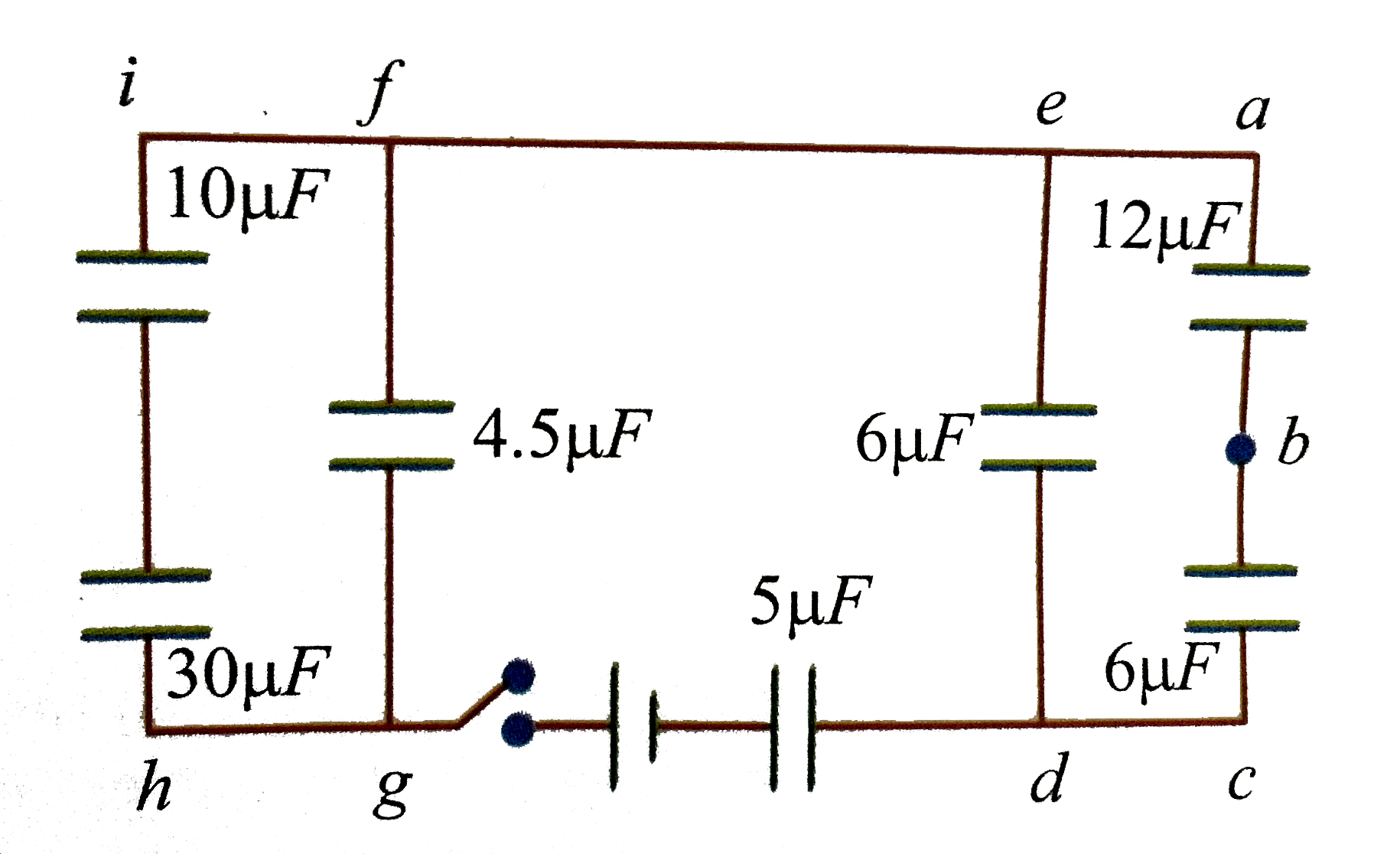
In the circuit diagram shown here seven capacitors are connected to a source of emf E. Initially, the switch S is closed and steady state attained. Now, the potential difference between the points 'a' and 'b' is 4 volt. Now, answer the following :
 .
.
The charge on 4.5μF is :A90μCB45μCC54μCDZero - Question 2 - Select One
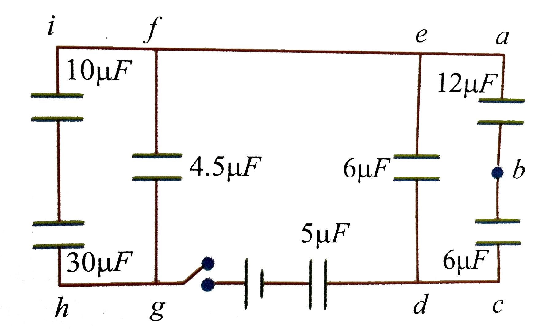
In the circuit diagram shown here seven capacitors are connected to a source of emf E. Initially, the switch S is closed and steady state attained. Now, the potential difference between the points 'a' and 'b' is 4 volt. Now, answer the following :
 .
.
The charge on 5μC is :A70μcB45μcC75μcD120μc - Question 3 - Select One
In the circuit diagram shown here seven capacitors are connected to a source of emf E. Initially, the switch S is closed and steady state attained. Now, the potential difference between the points 'a' and 'b' is 4 volt. Now, answer the following :
 .
.
The emf E of the battery is :A46 VB26 VC14 VD10 V
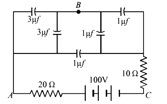
In the diagram shown find the potential difference between the points A and B and between the points B and C in the steady state.
 View Solution
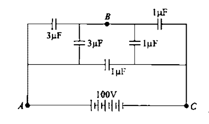
In circuit shown in figure calculate the potential difference between the points A and B and between the points B and C in the steady state.
 View Solution
The potential difference between the points A and B in the following circuit in steady state will be
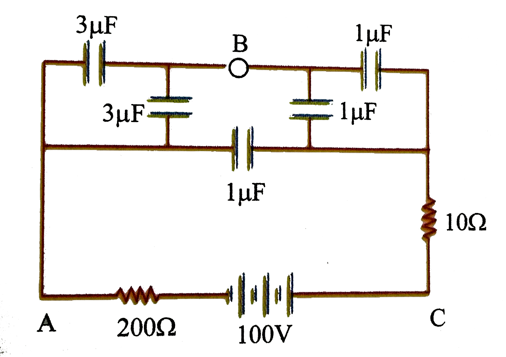 .View Solution
In the circuit shown in figure potential difference between the points A and B in the steady state is
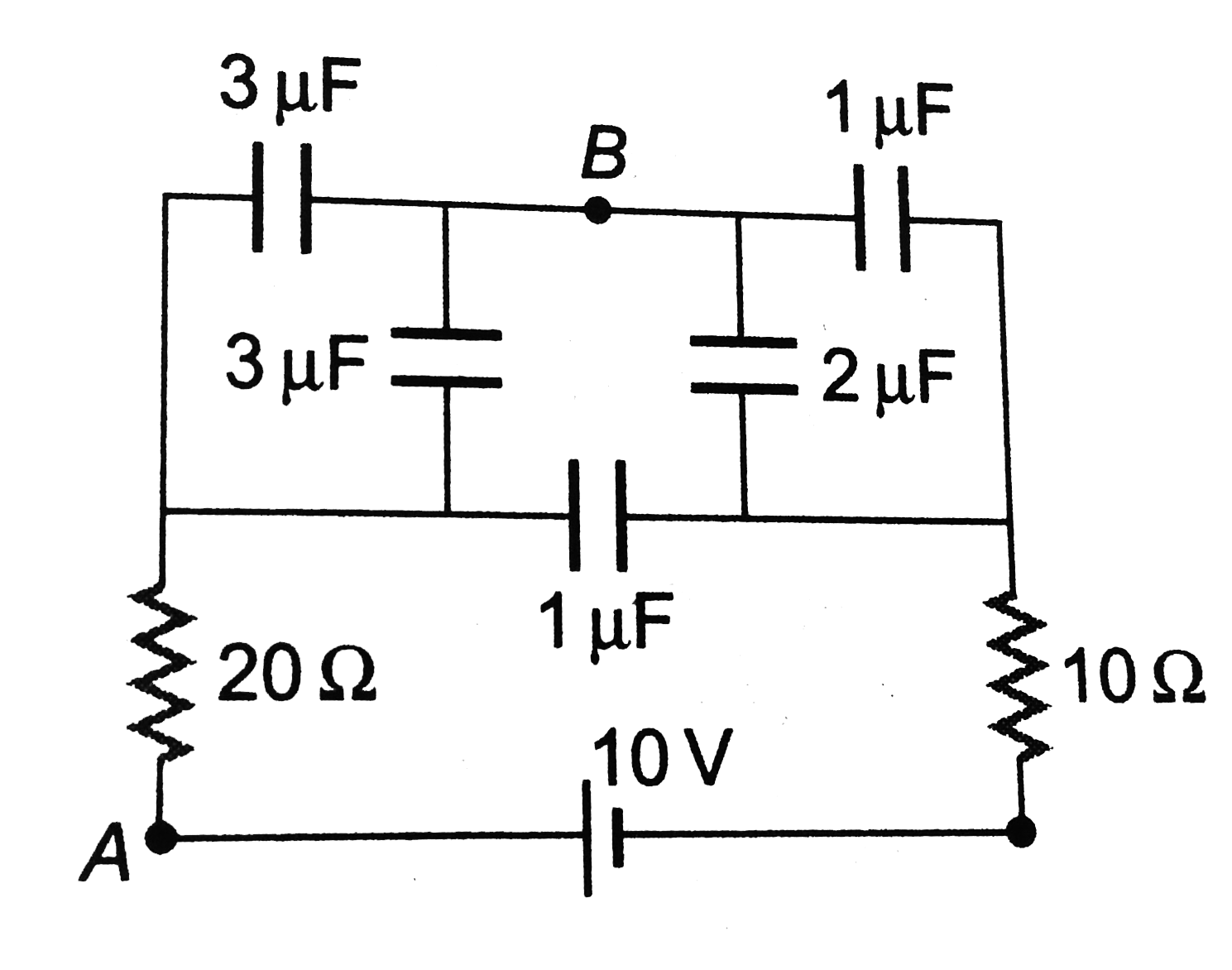 View Solution
In the circuit shown, charge on the capacitor connected between B and D at steady state is (initially all the capacitors are uncharged)
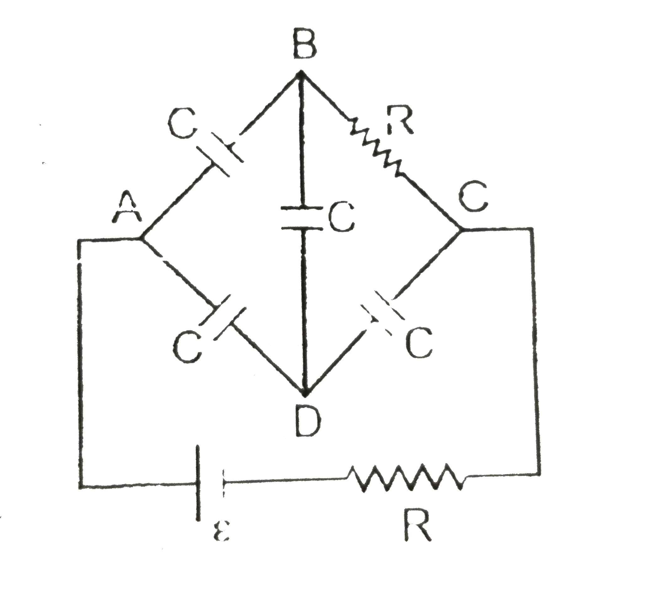 View Solution
