An uncharged capacitor of capacitance is connected in a circuit with two ideal batteries and two ideal ammeters G and G1 as shown. Both switches are initially open. Each option below details a possible pattern of closing the switches, and the consequent readings of the ammeters. Choose the correct option(s):
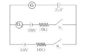
S1 is closed. After a long time interval, if S2 is closed while keeping S1 closed, initially G reads 1 A, and G1 reads zero
S1 is closed. After a long time interval, S2 is closed while keeping S1 closed. After another long time interval, G reads zero, and G1 reads 1.5A
Both S1 and S2 are closed simultaneously. Initially G reads 3 A, and G1 reads 2 A
Both S1 and S2 are closed simultaneously. After a long time interval, G reads zero, and G1 reads 0.5 A
The correct Answer is:A, C, D
Let the left and right junction be called P and Q respectively,
Case I: S1 is closed.
At steady state, Current through the capacitor has become zero and therefore, VP−VQ=20V. When S2 is closed, the potential difference across the capacitor cannot change immediately. So, initially VP−VQ remains 20V. Therefore using this we can deduce that initially, current through S1 is zero and current through S2 is 1A from right towards left.
Case II: S1andS2 are closed simultaneously.
Initially, the potential difference across the capacitor must be zero since it has no charge on it. hence initially, VP−VQ=0. using the we can find that initally, current through S1 is 2A from left towards right and current through S2 is 1 A from left towards right. therefore, by using KCL, we can find that current through the branch containing the capacitor is 3A from right towards left.
Similar Questions
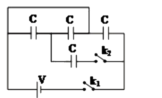
Four identical capacitors are connected with a battery of voltage V and two switches k1andk2 as shown in the figure below. Initially, k1 is closed, now if k2 is also closed, find the heat loss.
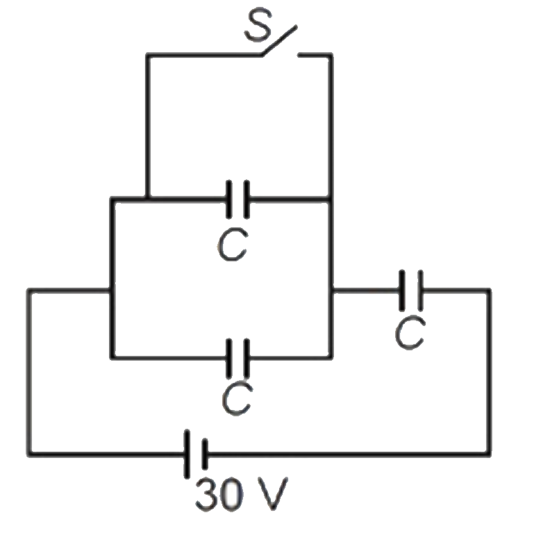
View SolutionThree capacitors each of capacitance C=2μF are connected with a battery of emf 30 V as shown in the figure . When the switch S is closed , the heat generated in the circuit will be
View Solution
Knowledge Check
If the switch at point P is opened (which was initially closed), choose the correct option (s).
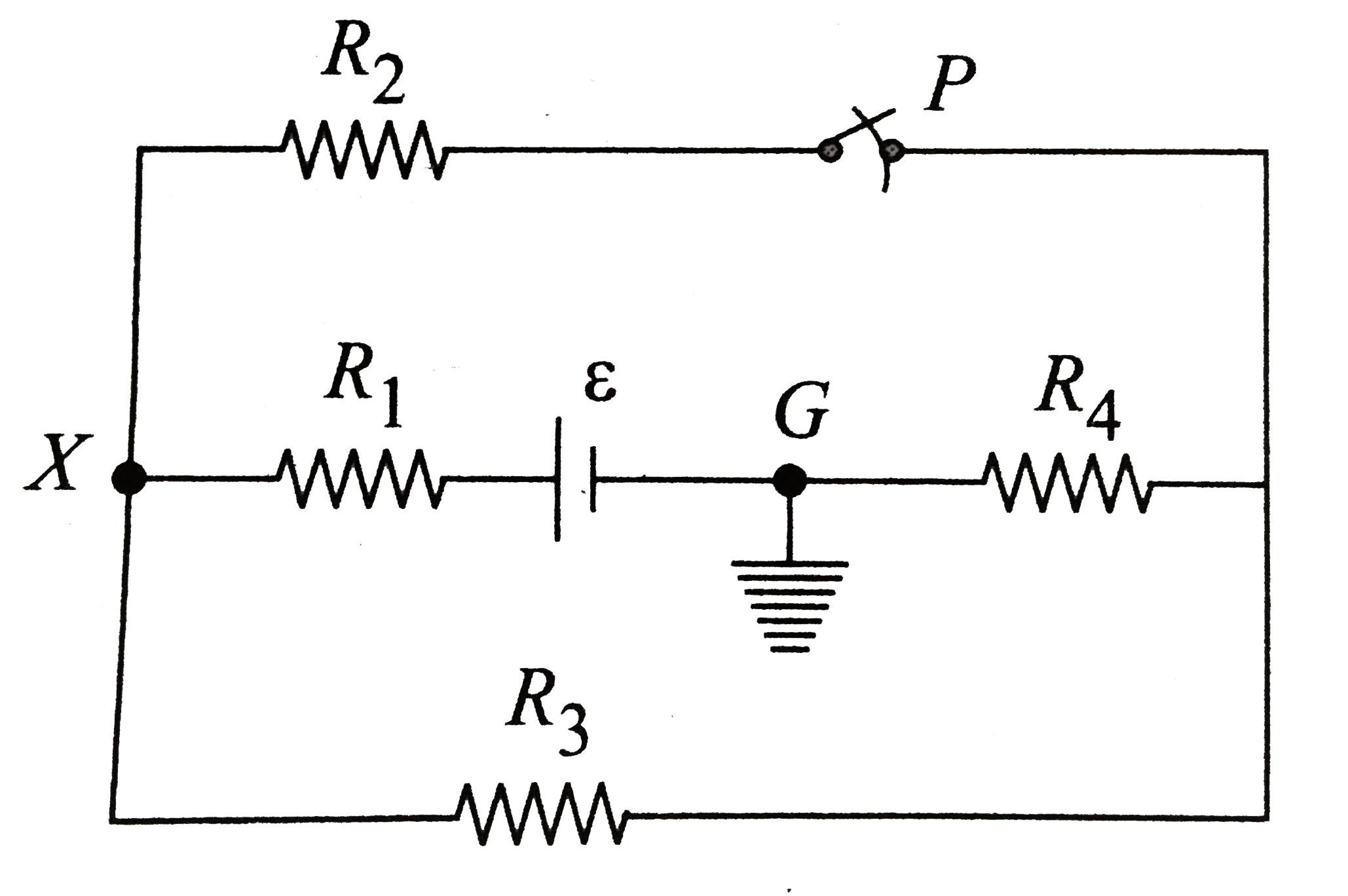 AThe current in R1 would not change.BThe potential difference between point X and the ground would increase.CThe current provided by the battery would decrease.DThe emf produced by the battery (assumed to have no internal resistance) would change.
In the circuit diagram shown in figure, initially switch S is opened and the circuit is in steady state. At time t=0, the switch S is closed and the new steady state is reached after some time. Choose the correct option(s)
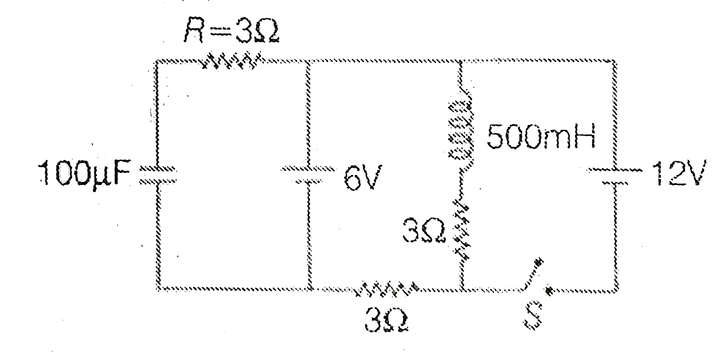 ACurrent in the indcutor when the circuit reaches the new steady state is 4A.BThe net change in the magnitic flux is the inductor is 1.5WbCThe net change in the magnetic flux in the conductor is 9volt when the circuit reaches the new steady state.DThe charge stored in the capacitor in the new steady state is 1.2mC
In the circuit shown, battery, ammeter , and voltmeter are ideal and the switch S is initially closed as shown. When switch S is opened
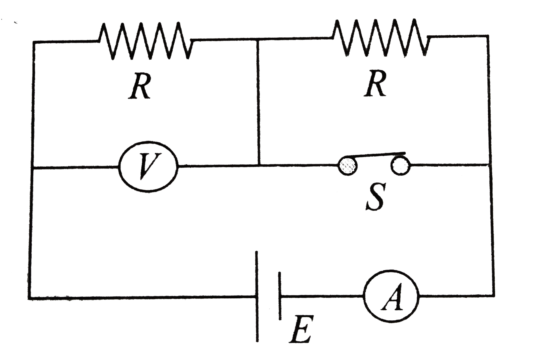 Aequivalent resistance across the battery increasesBpower dissipated by left resistance R increasesCvoltmeter reading decreasesDammeter reading decreases.
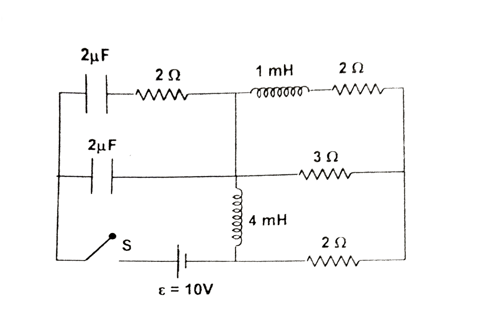
In the circuit shown, all the capacitors are initially uncharged. The current through the battery just after closing the switch 'S' is
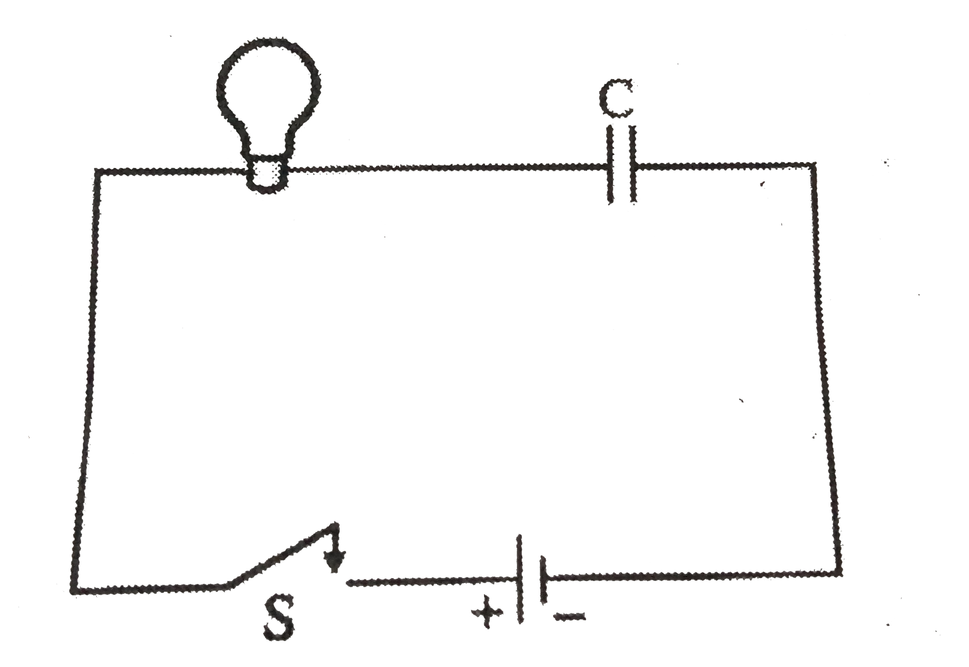
View SolutionA light bulb, a capacitor and a battery are connected together as shown here, with switch S initially open. When the switch S is closed, then which one of the following is true

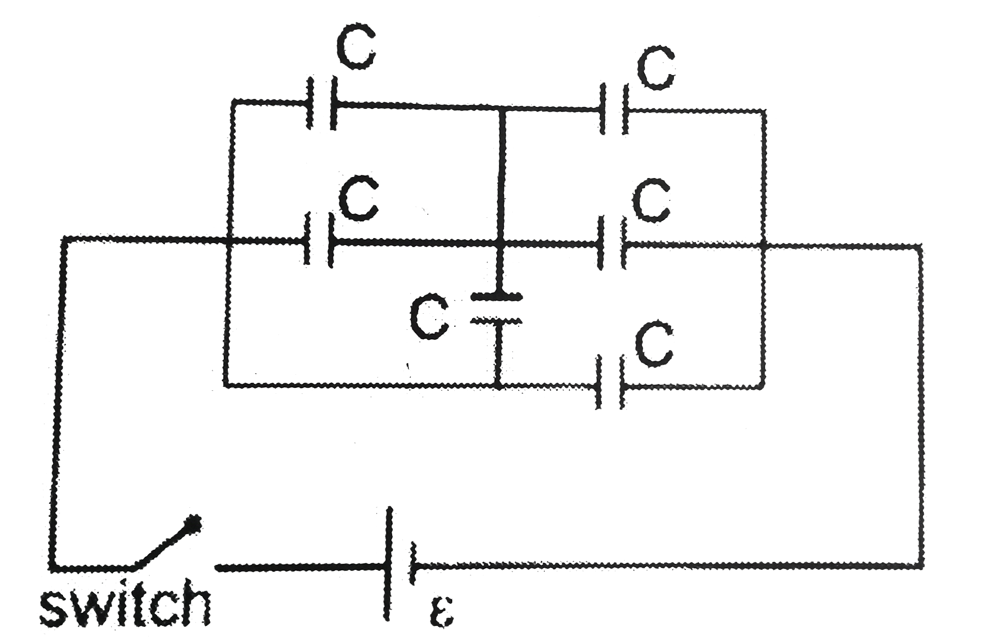
View SolutionSix capacitors each of capacitance 'C' is connected as shown in the figure and initially all the capacitors are uncharged . Now a battery of emf =ε is connected. How much charge will flow through the battery if the switch is on :
View SolutionA light bulb a capacitor and a battery are connected together as shown in figure, with switch S initially open. When the switch s is closed, which statement is true ?
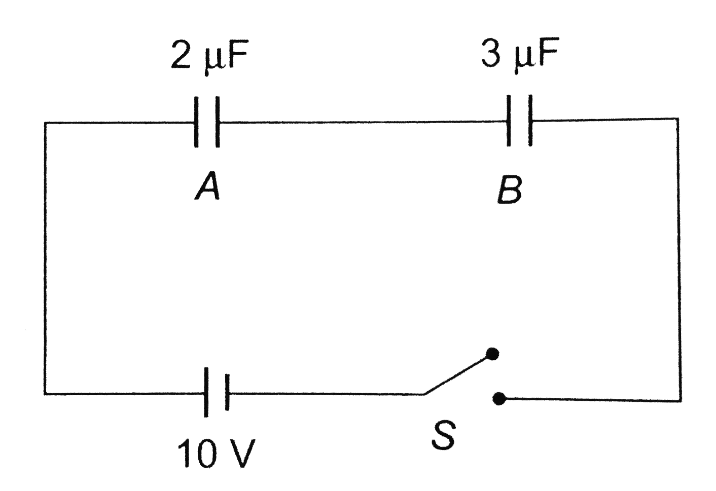
View SolutionTwo capacitors A and B are connected in series with a battery as shown in the figure. When the switch S is closed and the two capacitors get charged fully, then
View Solution