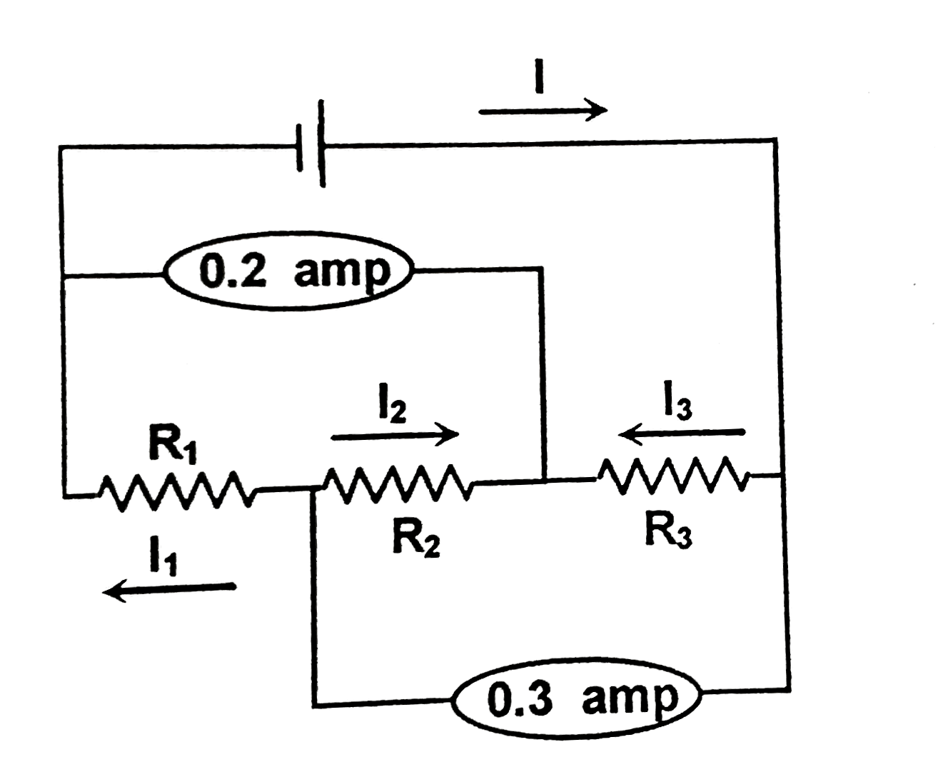
A circuit contains an ideal battery, three resistors and two ideal ammeters. The ammeters read 0.2 amp and 0.3 amp. After two of the resistor are switched (inerchanged) the readings of ammeter do not change. Then
If R2=R1,I1=I2=0.15A and I3=0.05A.
If R2=R1, the battery current is I=0.20A .
If R2=R3,I2=I3=0.1A and I1=0.2A.
If R2=R3, the battery current is I=0.4A.
The correct Answer is:A, C, D
a., c., d.
As the ammeters are ideal, we can conclude that the three
resistors R1,R2,andR are actually connected in parallel, the
equivalent resistance being
Req=R1R2R3R1R2+R1R3+R2R3
In the figure, the electric currents on each resistors and battery
are shown. The readings of the two ammeters are different and,
consequently, by simple symmetry considerations, resistors
R1andR3 are necessarily different. In other words, if we
interchange R1andR3, the readings of the ammeters will also
be interchanged. Therefore, we have two possible alternatives.
R2=R1 (if resistors R2andR1 switched, the readings of the
ammeters do not vary) or R2=R3(R2 and R3 can be switched
and the ammeters do not change.) The two solutions are :
If R2=R1 we obtain I2=I3=0.1A and I1=0.2A, and the
battery current is I=0.4A.
Similar Questions
Knowledge Check
- Question 1 - Select One or More
A circuit contains an ideal battery, three resistors and two ideal ammeters. The ammeters read 0.2 amp and 0.3 amp. After two of the resistor are switched (inerchanged) the readings of ammeter do not change. Then
 AIf R2=R1,I1=I2=0.15A and I3=0.05A.BIf R2=R1, the battery current is I=0.20A .CIf R2=R3,I2=I3=0.1A and I1=0.2A.DIf R2=R3, the battery current is I=0.4A.
 - Question 2 - Select One
In the circuit of figure A1 and A2 are ideal ammeters. Then the reading in ammeter A2 is
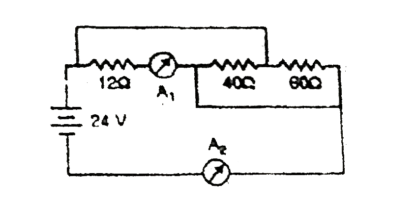 A0.4AB0.6AC2.0AD3.0A
 - Question 3 - Select One
In the circuit shown, the reading of the ammeter if diode is not ideal, will be
 A0B15mAC>15mAD<15mA
Redraw the circuit of Q.12, putting in an ammeter to measure the current through the resistors and a voltmeter to measure the voltage across the 12ohm resistor. What would be the readings in the ammeter and the voltmeter ?
View SolutionRedraw the circuit, putting in an ammeter to measure the current through the resistors and a voltmeter to measure the potential difference across the 12Ω resistor. What would be the readings in the ammeter and the voltmeter?
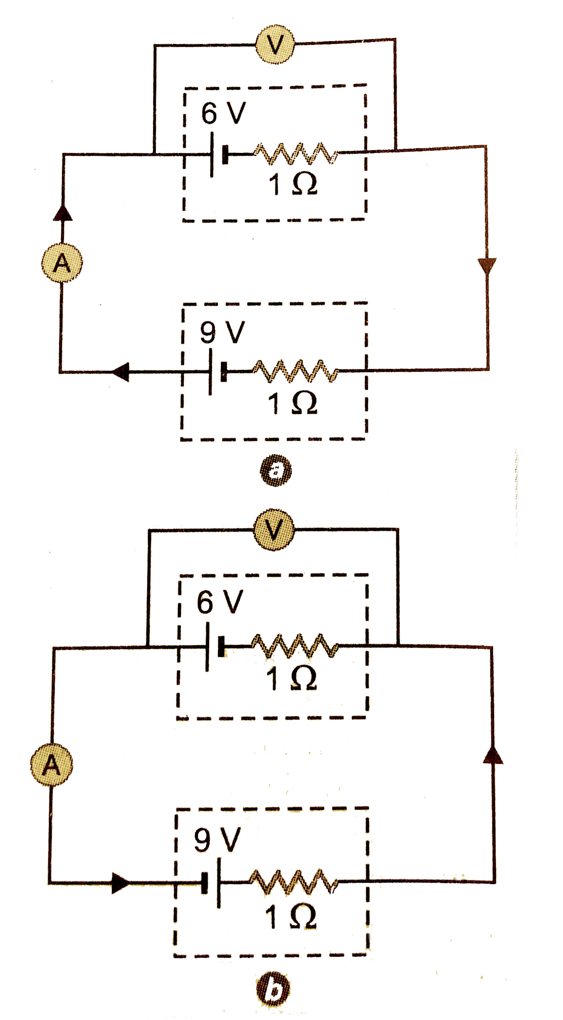
View SolutionIn the two electron circuit determine the readings of ideal ammeter (A) ideal voltmeter (V)
 View Solution
A circuit contains an ammeter, a battery of 30V and a resistance 40.8ohm all connected in series. If the ammeter has a coil of resistance 480ohm and a shunt of 20ohm, the reading in the ammeter will be
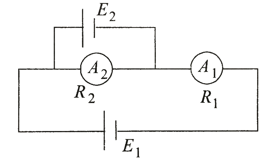
View SolutionTwo ideal batteries and two ammeters are arranged as shows in Fig. 6.67.
 View Solution


