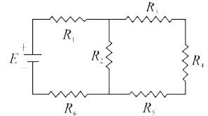
In the figure shown, what is the current (in Ampere) drawn from the battery? You are given: R1=15ΩR2=10ΩR3=5ΩR4=5ΩR5=25ΩR6=30Ω,E=150V
13/24
20/3
54/19
9/32
Step by step video & image solution for In the figure shown, what is the current (in Ampere) drawn from the battery? You are given: R_1=15Omega R_2=10Omega R_3 =5Omega R_4=5Omega R_5=25Omega R_6=30Omega,E=150V by Physics experts to help you in doubts & scoring excellent marks in Class 12 exams.
Updated on:21/07/2023Similar Questions
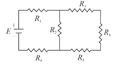
In the figure shown, what is the current (in Ampere) drawn from the battery? You are given:
R1=15Ω,R2=10Ω,R3=20Ω,R4=5Ω,R5=25Ω,R6=30Ω,E=15V
View SolutionIn Fig. 27-43, the current in resistance 6 is i6=2.80A the resistances are R1=R2=R3=2.00Ω,R4=16.0Ω,R5=8.00ΩandR6=4.00Ω. Wat is the emf of the ideal battery?

View Solution
Knowledge Check
The potential difference in volt across the resistance R3 in the circuit shown in figure, is (R1=15Ω,R2=15Ω,R3=30Ω,R4=35Ω)
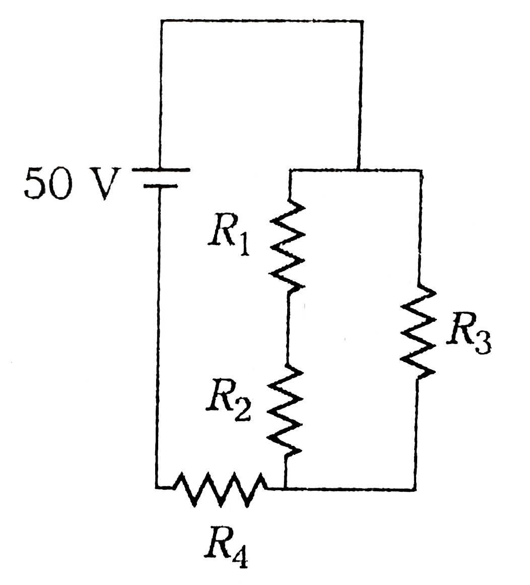 A5B7.5C15D12.5
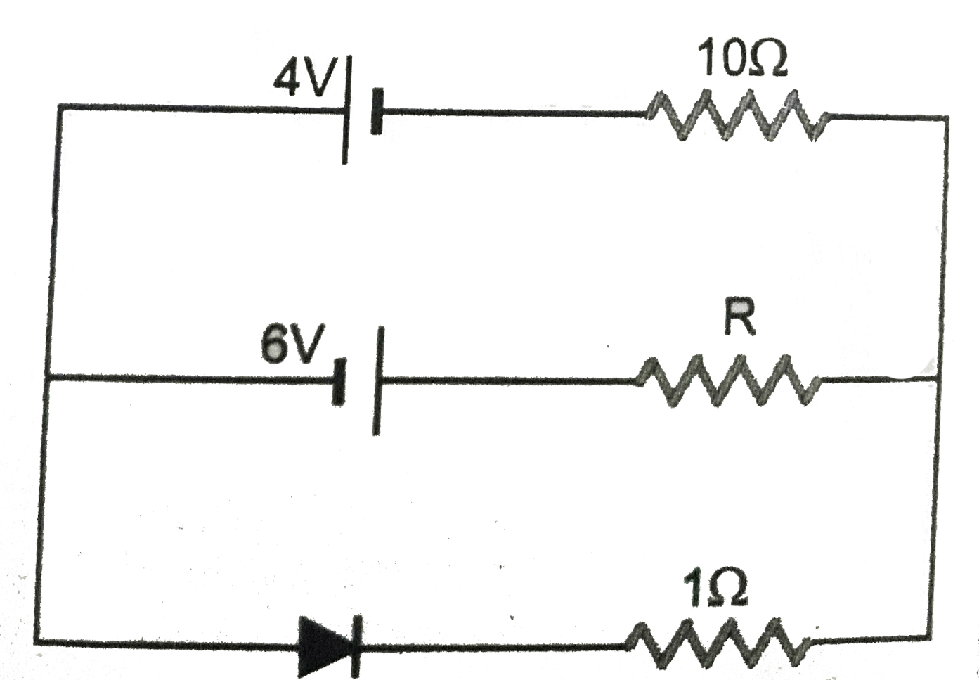
Find the current through the resistance R in Fig if R=10Ω and R=20Ω.
View SolutionDetermine the voltage drop across the resistor R1 in the circuit given below with E = 65V, R_1 = 50 OmegaR_2 = 100 Omega, R_3 = 100 Omega, and R_4 300 Omega.
View Solution3 resistors R1,R2andR3 are connected in series to a battery. Draw the circuit diagram showing the arrangement. Derive an expression for the equivalent resistance of the combination.
(b) Resistors are given as R1=10Ω,R2=20ΩandR3=30Ω. Calculate the effective resistance when they are connected in series . Also calculate the current flowing when the combination is connected to a 6V battery.
View Solution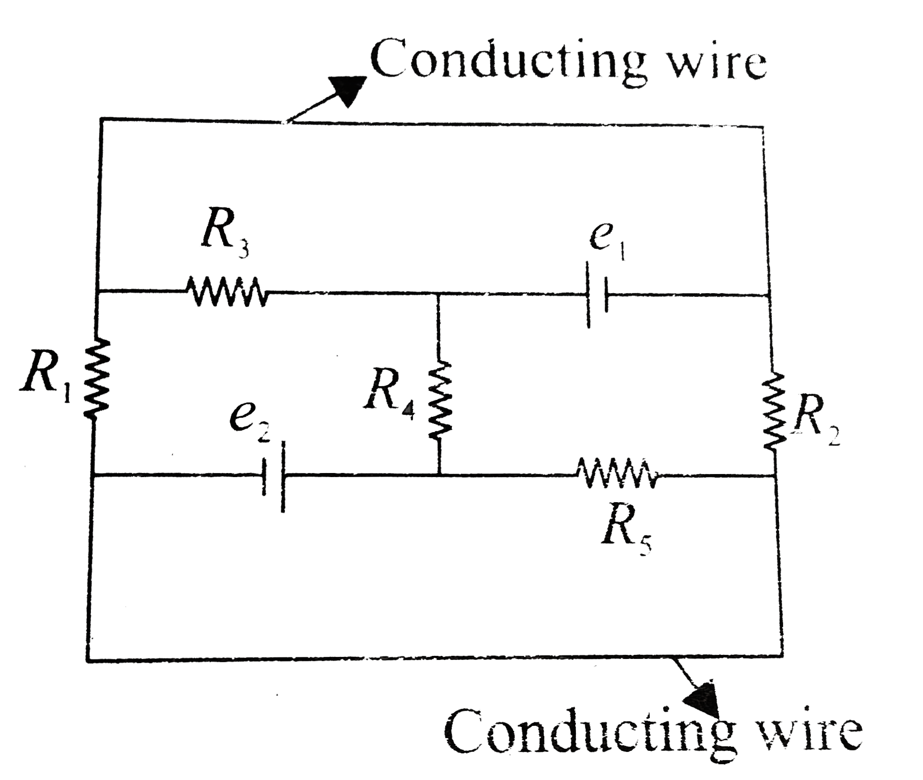
In the given cirucit, determine current through branch having indicated resistor R4 Given R1=R2=4Ω,R3=R4
R5=2Ωε1=5V,ε2=10V
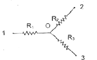
View SolutionFind the current flowing through the resistance R1 of the circuit shown in figure if the resistances are equal to R1=10Ω,R2=20ΩandR3,=30Ω and the potentials of the points 1, 2, and 3 are equal to φ1=10V,φ2=6Vandφ3=5V
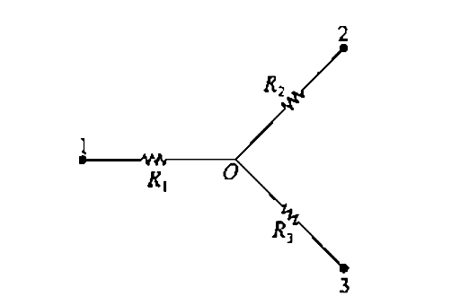
View SolutionFind the current flowing through the resistance R1 of the circuit shown in figure-3.103. the resistances are equal to R1=10Ω,R2=20Ω and R3=30Ω and the potentials of points 1,2 and 3 are given as V1=10V,V2=6V and V3=5V.
View SolutionFind the current in each wire.
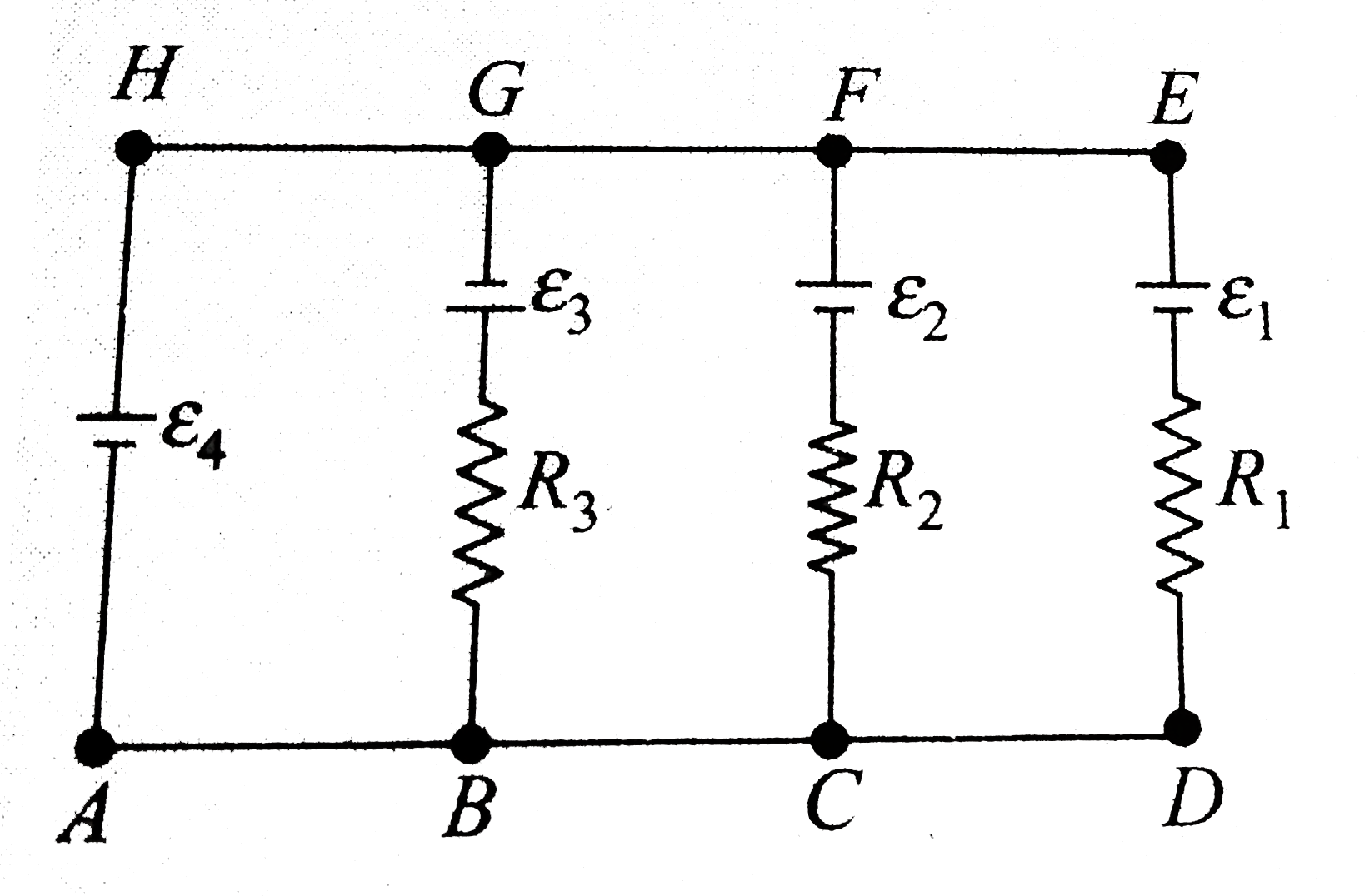
ε1=50V,ε2=40V
ε3=30V,ε4=10V
R1=2Ω,R2=2Ω
R3=1Ω
View Solution
