RC Circuits and their characteristics| charging the RC circuit
Step by step video solution for RC Circuits and their characteristics| charging the RC circuit by Physics experts to help you in doubts & scoring excellent marks in Class 12 exams.
Updated on:21/07/2023Similar Questions
Knowledge Check
Two identical resistors of magnitude R and two identical capacitors of magnitude C are used to form an RC circuit. In which case the time constant of the RC circuit is the highest?
ATwo resistors and two capacitors connected in series with a power supply.BTwo resistors and two capacitors connected in parallel with a power supply.CTwo resistors connected in parallel, two capacitors connected in parallel, and those two combinations are in series with a power supplyDTwo resistors connected in series, two capacitors connected in parallel and those two combinations are connected in series with a power supply.Two identical resistors of magnitude R and two identical capacitors of magnitude C are used to form an RC circuit. In which case the time constant of that RC circuit is the highest?
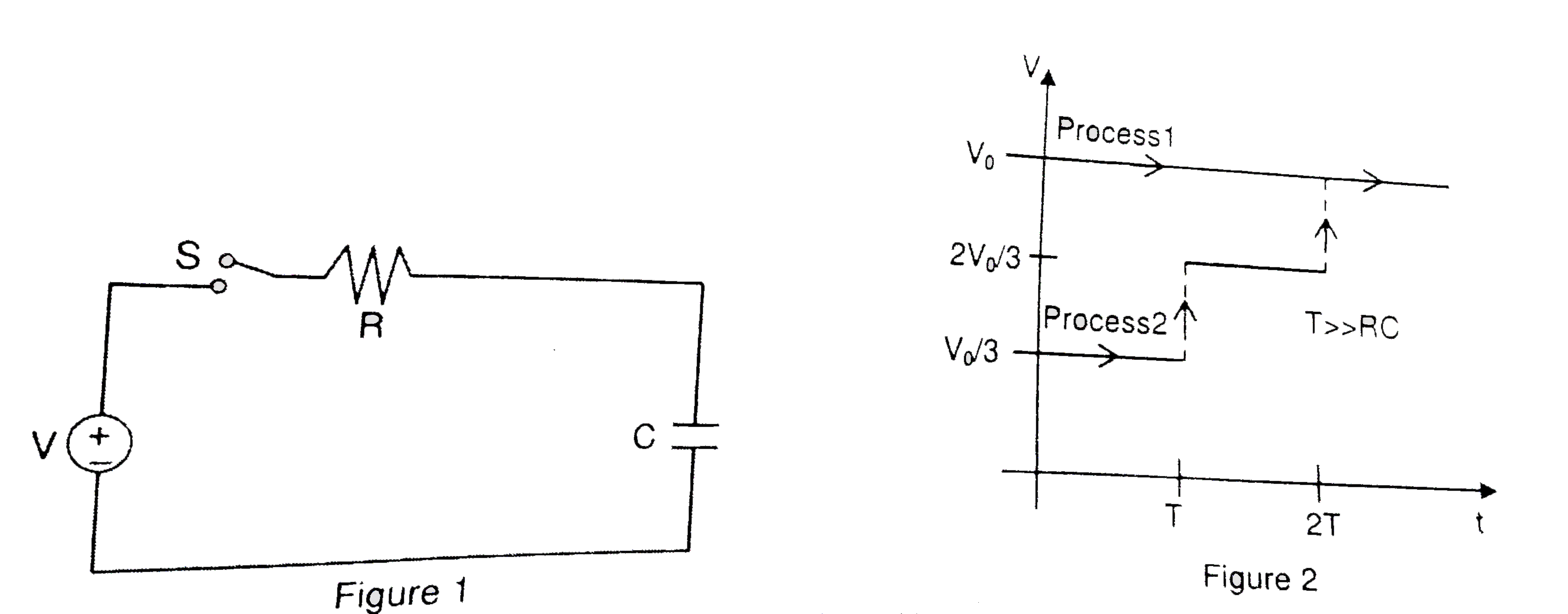
ATwo resistors and two capacitors connected in series with a power supplyBTwo resistors and two capacitors connected in parallel with a power supplyCTwo resistors connected in parallel, two capacitors connected in parallel, and those two combinations are connected in series with a power supplyDTwo resistors connected in series, two capacitors connected in parallel, and those two combinations are connected in series with a power supplyConsider a simple RC circuit as shown in figure 1.
Process 1 : In the circuit the switch S is closed at t=0 and the capacitor if fully charged to voltage V0 (i.e., charging continues for time T>>RC). In the process some dissipation (ED) occurs across the resistance R. The amount of energy finally stored in the fully charged capacitor is Ec.
Process 2 : In a different process the voltage is first set to V03 and maintained for a charging time T>>RC. Then the voltage is raised to 2C03 without discharging the capacitor and again maintained for a time T>>RC. The process is repeated one more time by raising the voltage to V0 and the capacitor is charged to the same final voltage V0 as in Process 1.
These two processes are depicted in figure 2.

In process 2, total energy dissipated across the resistance ED is :AED=3(12CV20)BED=13(12CV20)CED=3CV20DED=12CV20
Series RC and RL circuit
View SolutionA capacitor and resistor of 12Ω are connected in series with an AC supply 100 V, 50 Hz . Calculate the capacitance of the capacitor if power factor of the RC circuit is 0.8.
View SolutionHow many time constants will elapse before the current in a charging RC circuit drops to half of its initial value?Answer the same question for a discharging RC circuit.
View SolutionHow many time constants will elapse before the energy stored in the capacitor reaches half of its equilibrium value in a charging RC circuit ?
View SolutionIn a series RC circuit with an AC source, R=300Ω,C=25μF,ε050V and v=50(Π)Hz. Find the peak current and the average power dissipated in the circuit.
View Solution
