RC Circuit
Step by step video solution for RC Circuit by Physics experts to help you in doubts & scoring excellent marks in Class 12 exams.
Updated on:21/07/2023Similar Questions
Combination of circuit |RC and LR Circuit| Phasor diagram
View SolutionAn a.c. voltage V=Vm sin ωt is applied across a
(i) series RC circuit in which the capacitive impedance is 'a' times the resistance in the circuit,
(ii) series RL circuit in which the inductive impedance is 'b' times the resistance in the circuit. Calculate the value of the power factor of the circuit in each case.
View Solution
Knowledge Check
In an RC circuit while charging, the graph of 1ni versis time is as shown by the dotted line in the diagram figure. Where i is the current. When the value of the resistance is doubled, which of the solid curve best represents the variation of 1ni versus time
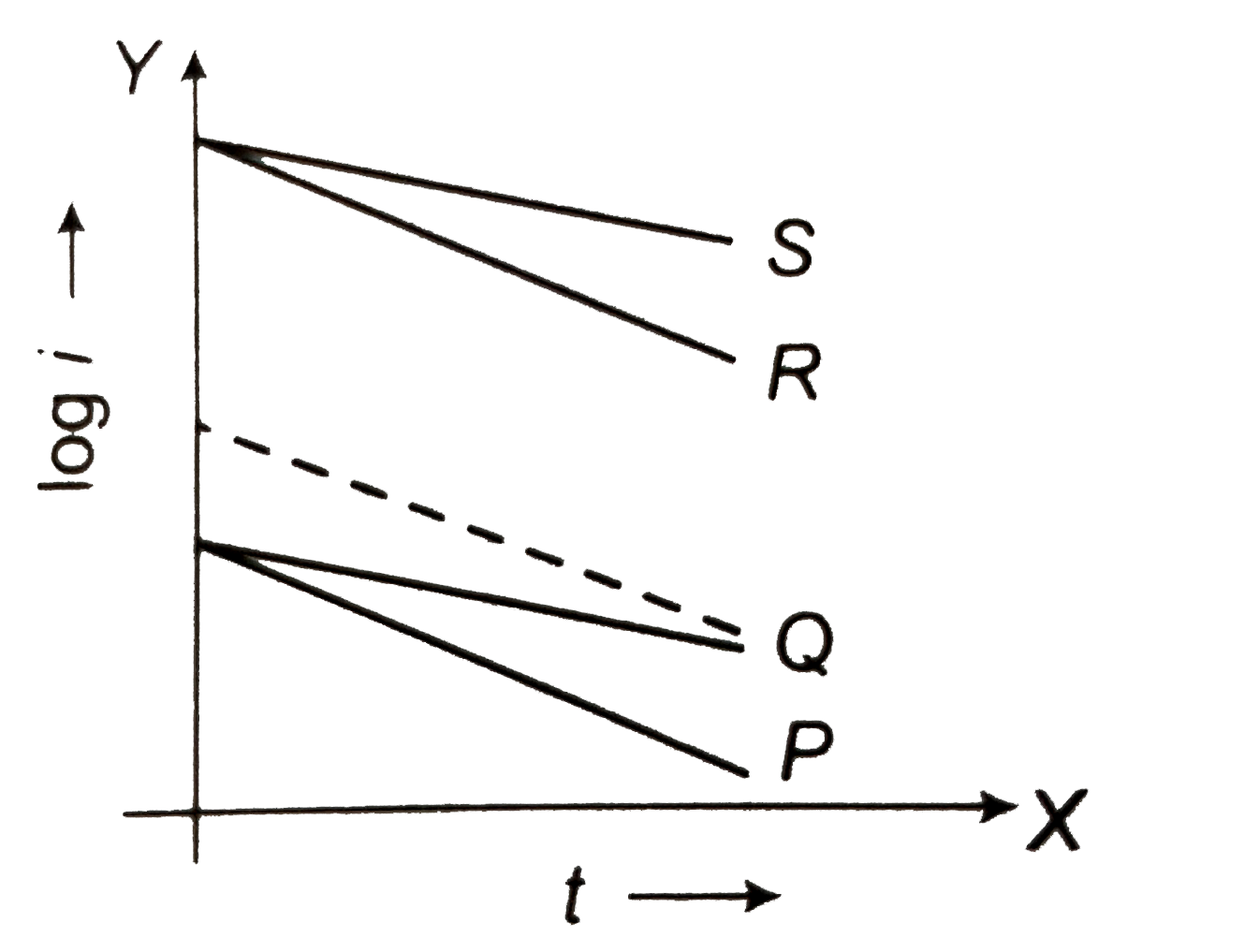 APBQCRDS
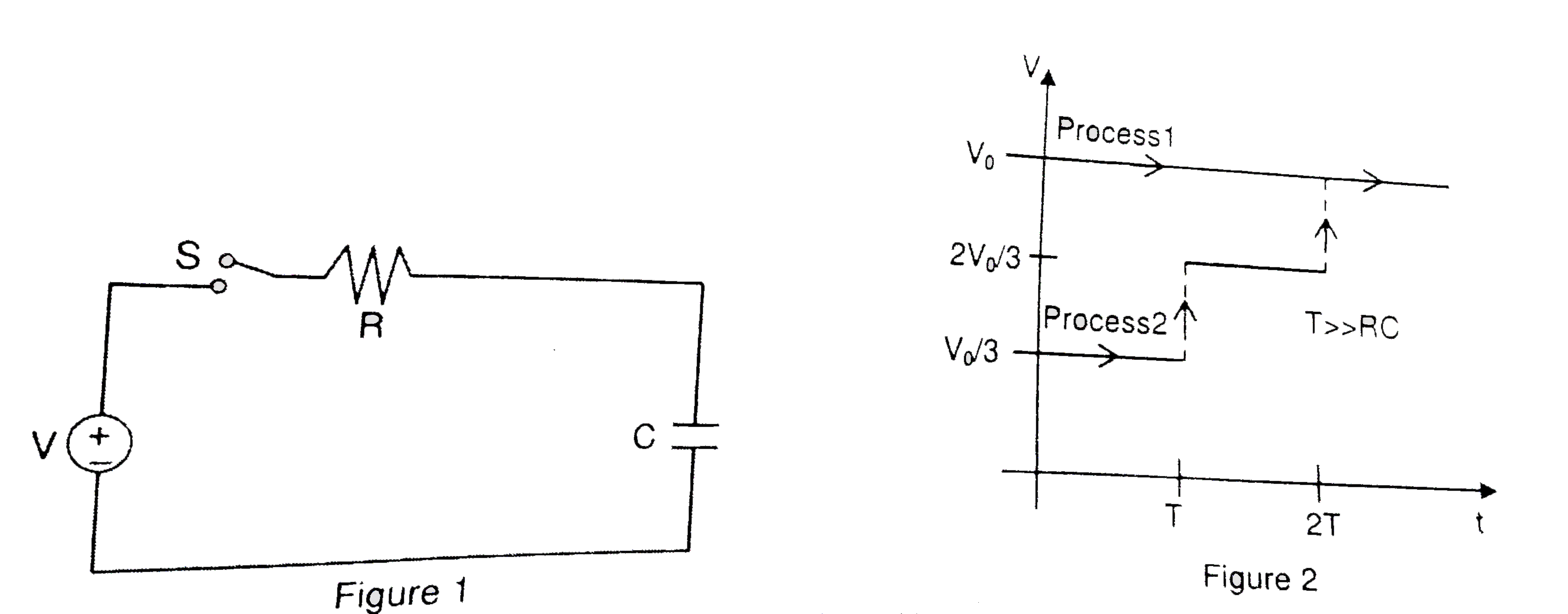
Consider a simple RC circuit as shown in figure 1.
Process 1 : In the circuit the switch S is closed at t=0 and the capacitor if fully charged to voltage V0 (i.e., charging continues for time T>>RC). In the process some dissipation (ED) occurs across the resistance R. The amount of energy finally stored in the fully charged capacitor is Ec.
Process 2 : In a different process the voltage is first set to V03 and maintained for a charging time T>>RC. Then the voltage is raised to 2C03 without discharging the capacitor and again maintained for a time T>>RC. The process is repeated one more time by raising the voltage to V0 and the capacitor is charged to the same final voltage V0 as in Process 1.
These two processes are depicted in figure 2.
In process 2, total energy dissipated across the resistance ED is :AED=3(12CV20)BED=13(12CV20)CED=3CV20DED=12CV20Consider a simple RC circuit as shown in figure 1.
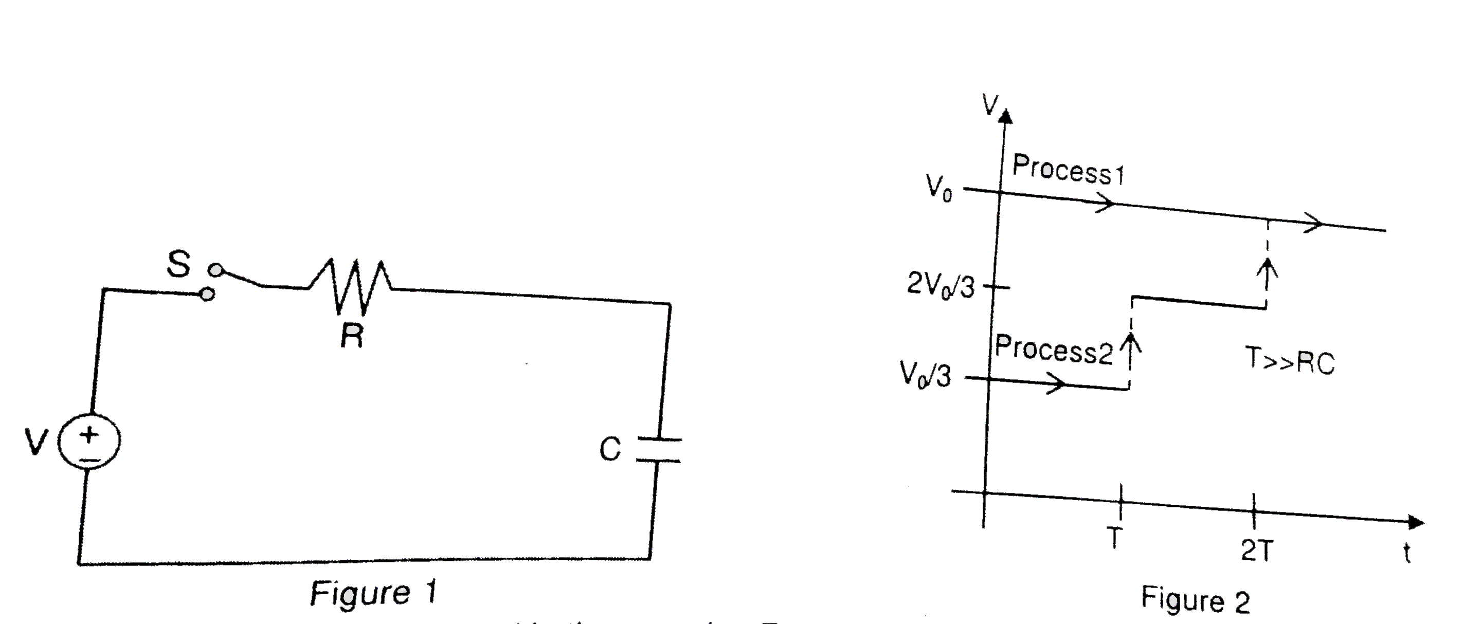
Process 1 : In the circuit the switch S is closed at t=0 and the capacitor if fully charged to voltage V0 (i.e., charging continues for time T>>RC). In the process some dissipation (ED) occurs across the resistance R. The amount of energy finally stored in the fully charged capacitor is Ec.
Process 2 : In a different process the voltage is first set to V03 and maintained for a charging time T>>RC. Then the voltage is raised to 2C03 without discharging the capacitor and again maintained for a time T>>RC. The process is repeated one more time by raising the voltage to V0 and the capacitor is charged to the same final voltage V0 as in Process 1.
These two processes are depicted in figure 2.
In process 1, the energy stored in the capacitor Ec and heat dissipated across resistance ED are related by :AEc=12EDBEc=EDln 2CEc=2EDDEc=ED
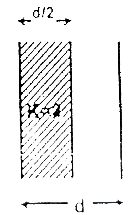
A certain series RC circuit is formed using a resistance R, a capacitor without dieiectric having a capacitance C=2F and a battery of emf E=3V. The circuit is completed and it is allowed to attain the steady state. After this, at t=0, half the thickness of the capacitor is filed with a dielectric of constant K=2 as shown in the figure. The system is again allowed to attain a steady state. What will be the heat generated (in joule) in the capacitor between t=0 and t=∞ ?
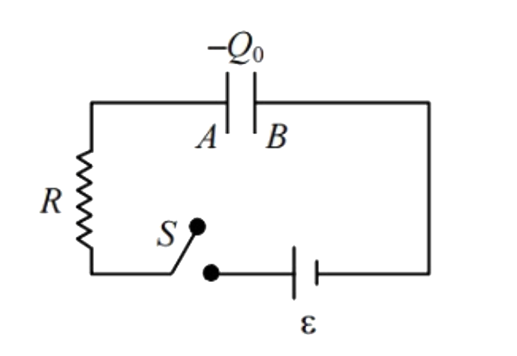
View SolutionThe figure shows an RC circuit with a parallel plate capacitor. Before switching on the circuit, plate A of the capacitor has a charge. −Q0 while plate B has no net charge. If at t=0, the switch is closed then after how much time (in seconds) will the net charge on plate A becomes zero? [Given : C=1μF,Q0=1mC,ε=1000VandR=2×1061n3Ω]
View SolutionParallel RC and Parallel RL Circuit
View SolutionShow that time constant (τ=RC) of R−C circuit has the dimensions of time.
View SolutionIn a series RC circuit, R = 30 ohm, C=0.25μF, V=100V,ω=10000rad/s. Find the current in the circuit and calculate the voltage across the resistor and capacitor. Is the algebraic sum of these voltages more than the source voltage ? If yes, resolve the paradox.
View Solution
