Switching and RC Circuits
Video Solution
|
Answer
Step by step video solution for Switching and RC Circuits by Physics experts to help you in doubts & scoring excellent marks in Class 12 exams.
Updated on:21/07/2023Similar Questions
Knowledge Check
Resistor of resistance R and a capacitor of capacitance Care connected in series to a battery of emf E, through a switch and this circuit is called A. Similarly, inductor of inductance L and resistor of resistance R are connected in series to a battery of emf Ethrough a switch and this circuit is called B. Switches in both the circuits A and B are closed at t= 0.
ACurrent in circuit A is E/R just after t = 0BCharge on capacitor long after t = 0 is CECCurrent in circuit B is just after t = 0DCurrent through inductor long after t = 0 is E/RWhich of the following is possible application of an RC circuit?
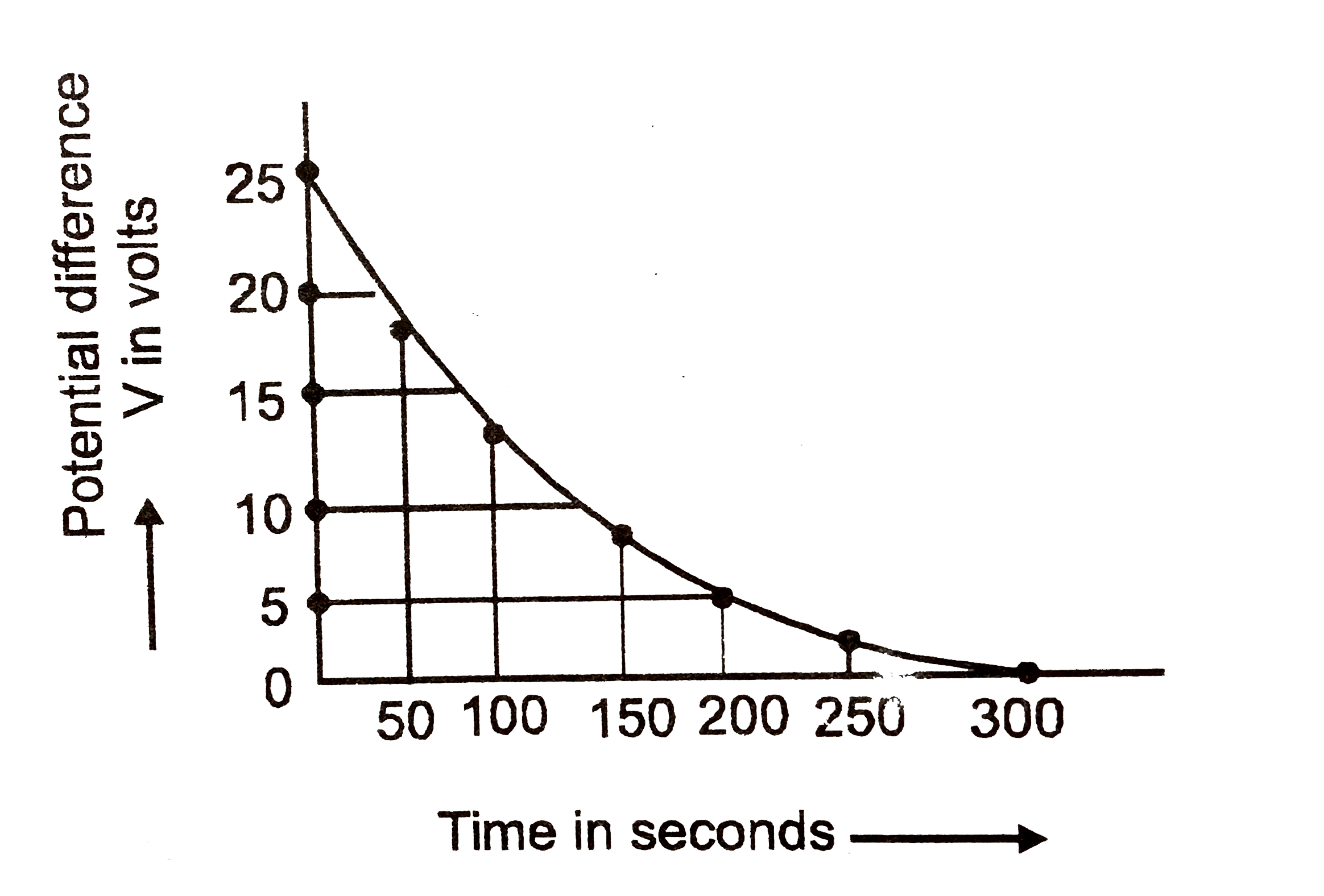
AWindshield wipersBFlashing red lights on roadway construction sitesCHeart pacemakersDAll of theseThe figure shows an experimental plot discharging of a capacitor in an RC circuit. The time constant of this circuit lies between:
 A150secand 200secB0 and 50secC50sec and 100secsD100sec and 150sec
Dielectric inside capacitor and Introduction to RC Circuit
View SolutionCombination of circuit |RC and LR Circuit| Phasor diagram
View SolutionHow many time constants will elapse before the current in a charging RC circuit drops to half of its initial value?Answer the same question for a discharging RC circuit.
View SolutionShow the switch signs in circuit in (i) open(ii) closed circuit,
View SolutionThe electric curren in a charging R-C circuit is given by i=i0e−tRC when i0, R and C aere constant parameters of the circuit and t is time. Find the rate of change of current at a.t=0,b.t=RCc.t=10RC.
View Solution
