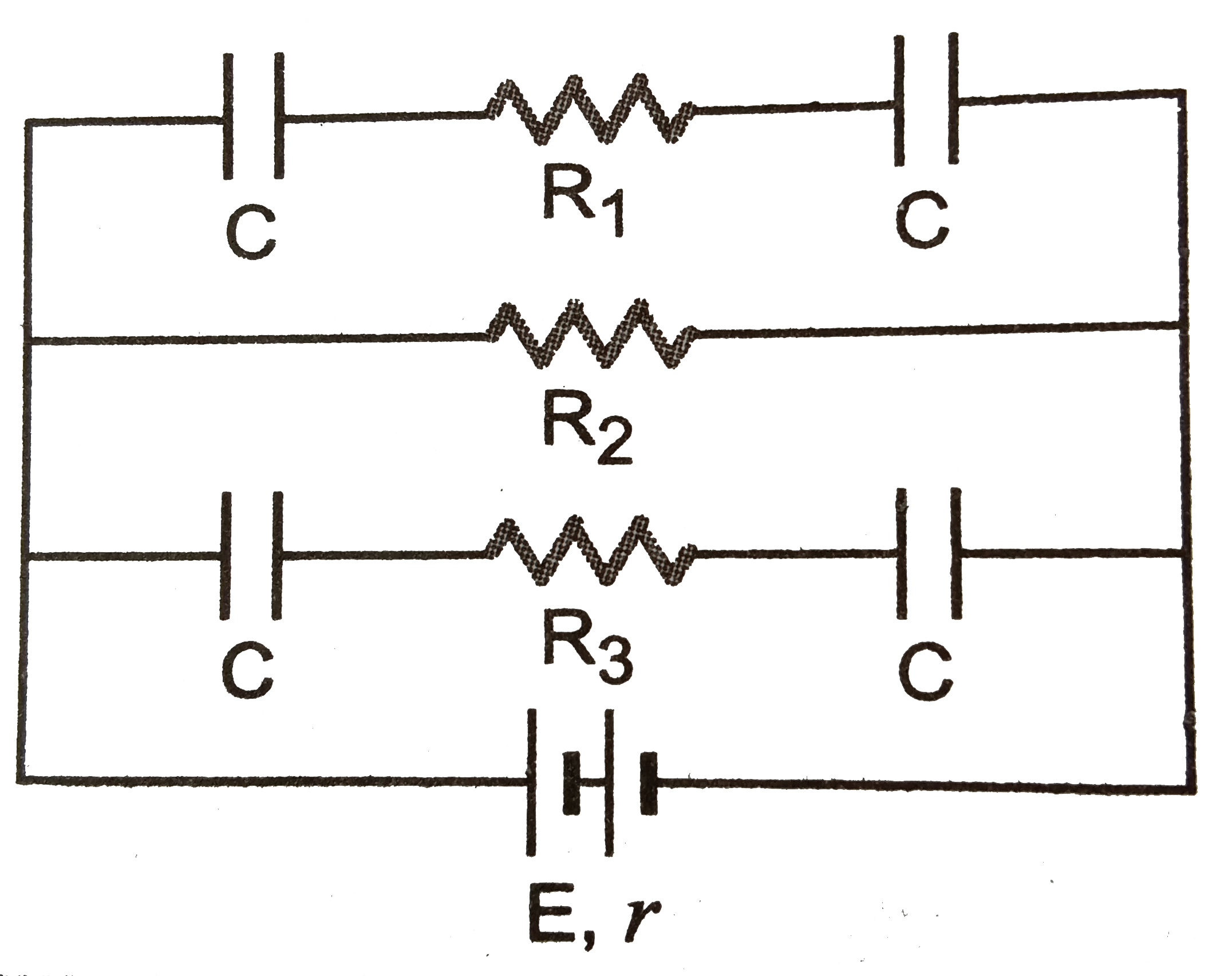
In Fig, E=5 volt , r=1Ω,R2=4Ω,R1=R3=1Ω and C=3μF. Then the numbercal value of the charge on each plate of the capacitor is
24μC
12μC
6μC
3μC
The correct Answer is:C
Step by step video & image solution for In Fig, E =5 volt , r = 1 Omega, R_(2) = 4 Omega, R_(1) = R_(3) = 1 Omega and C = 3 muF. Then the numbercal value of the charge on each plate of the capacitor is by Physics experts to help you in doubts & scoring excellent marks in Class 12 exams.
Updated on:21/07/2023Topper's Solved these Questions
Similar Questions
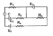
In the given circuit. E1=6vo<s,E2=2vo<s,E3=6vo<s
R1=6ΩR2=2ΩR3=4Oemga,R4=3Ω and C=5μF. Find the current in R3 and energy stored in the capacitor at steady state
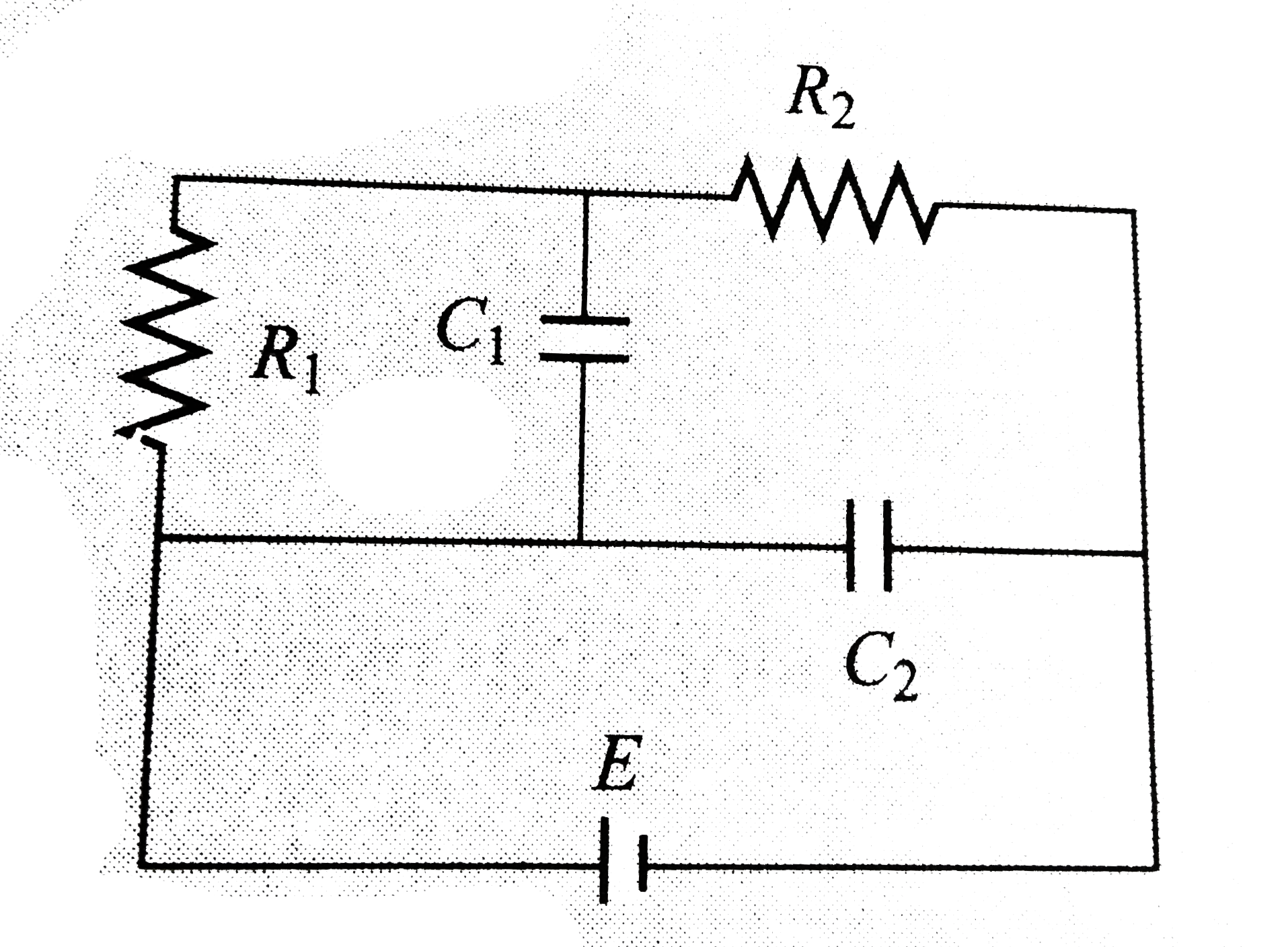
View SolutionIn the circuit shown in fig. R1=10Ω,R2=Ω,C1=1μF,C2=2μF, and E =6V. Calculate the charge on each capactor in the stedy state.
View Solution
Knowledge Check
In Fig, E=5 volt , r=1Ω,R2=4Ω,R1=R3=1Ω and C=3μF. Then the numbercal value of the charge on each plate of the capacitor is
 A24μCB12μCC6μCD3μC
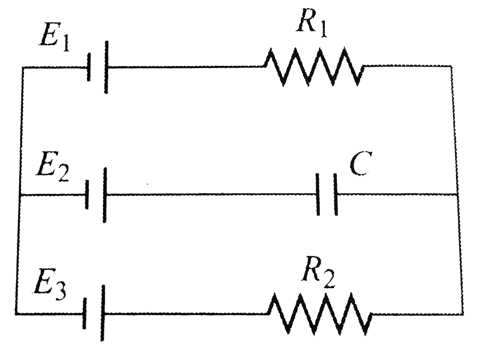
In the circuit shown , the batteries have emf E1=E2=1V,E3=2.5V, and the resistance R1=10Ω,R2=20Ω, Capacitance C=10μF. The charge on the left plate of the charge on the left plate of the capacitor C at steady state is
 A+2μCB−4μCC−5μCD+12μC
Figure shows a battery with emf 15 V in a circuit with R1=30Ω,R2=10Ω,R3=20Ω and capacitance C=10μF. The switch S is initially in the open position and is then closed at time t= 0. What will be the fimal steady - state charge on capacitor?
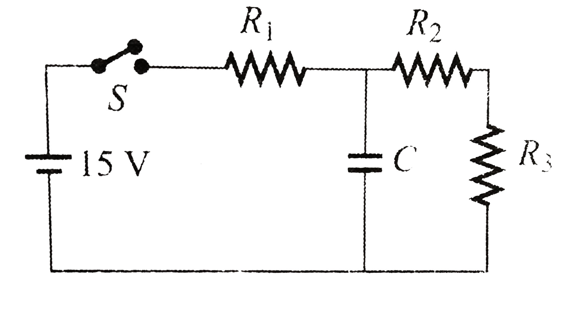 A75μCB50μCC10μCDnone of these
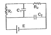
In the circuit shown in figure, R(1)=1Ω,R2=2Ω,C1=1μF,C2=2μF and E=6V. Calculate charge on each capacitor in steady state
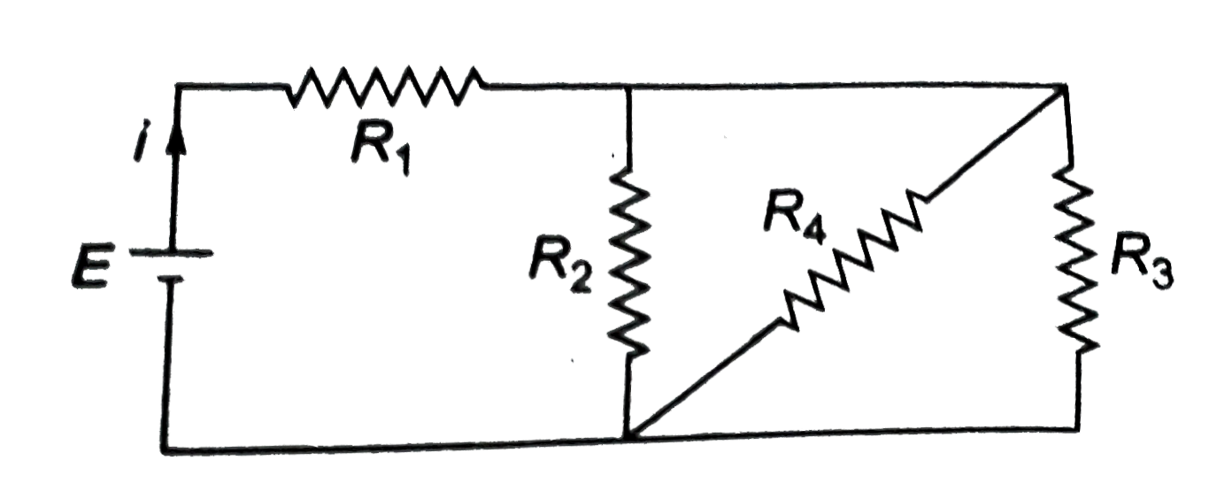
View SolutionIn the circuit given E = 6.0 volt, R1=100Ω,R2=R3=50Ω and R4=75Ω. The equivalent resistance of the circuit, in ohms is
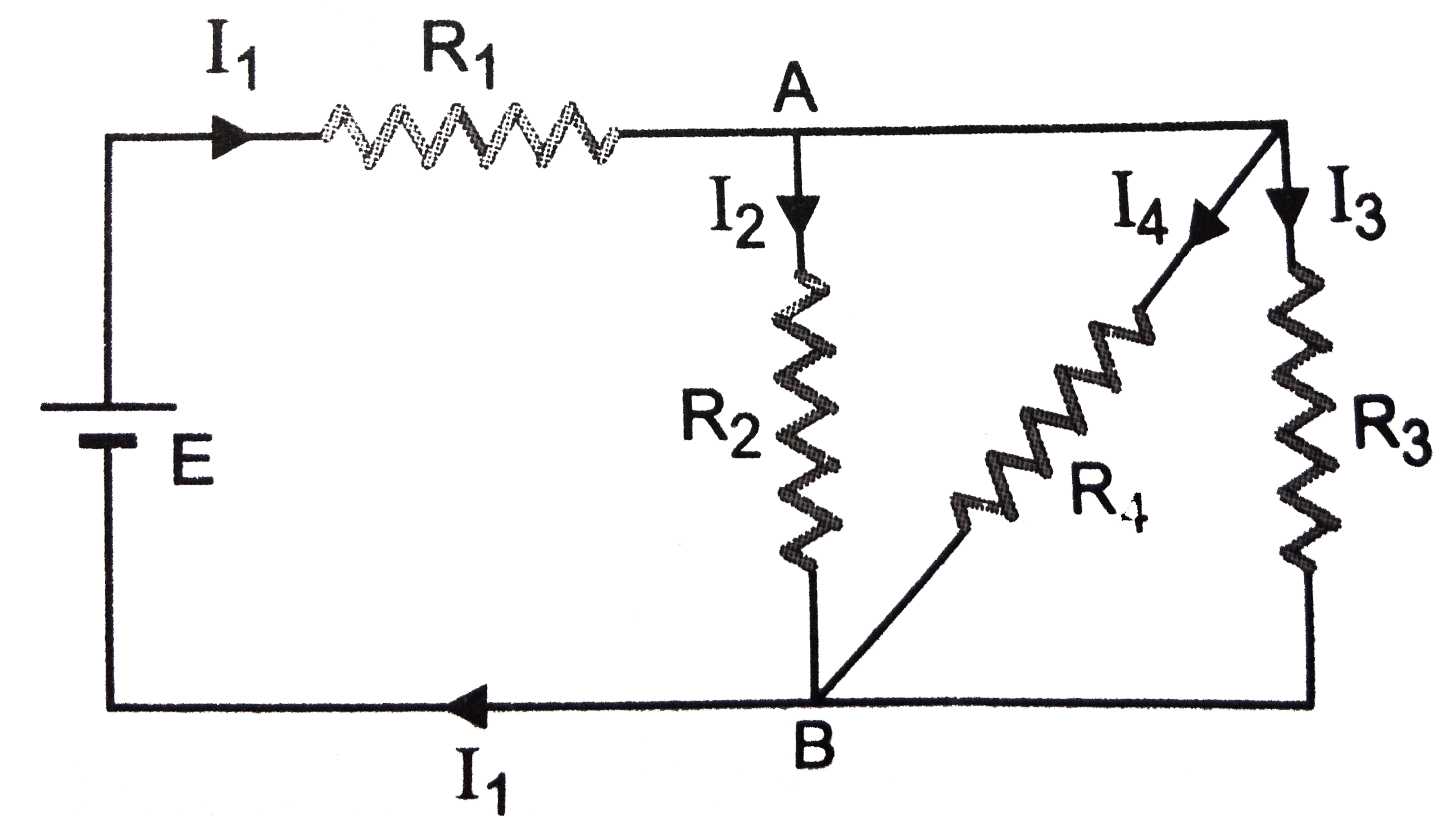
View SolutionIn the circuit R1=4Ω,R2=R3=15ΩR4=30ΩandE=10V Calculate the equivalent resistance of the circuit and current in each resistor
View SolutionIf in the figure R1=10Ω,R2=40Ω,R3=30Ω,R4=20Ω,R5=60Ω and a 12 V battery is connected to the arrangement, calculate (i) the total resistance in the circuit and (ii) the total current flowing in the circuit.
View SolutionIn the circuit shows in Fig E=15V, R1=1Ω, R2=1Ω, R3=2Ω, and L=1.5H. The currents flowing through R1,R2,and R3 are i1,i2, and i3, respectively.
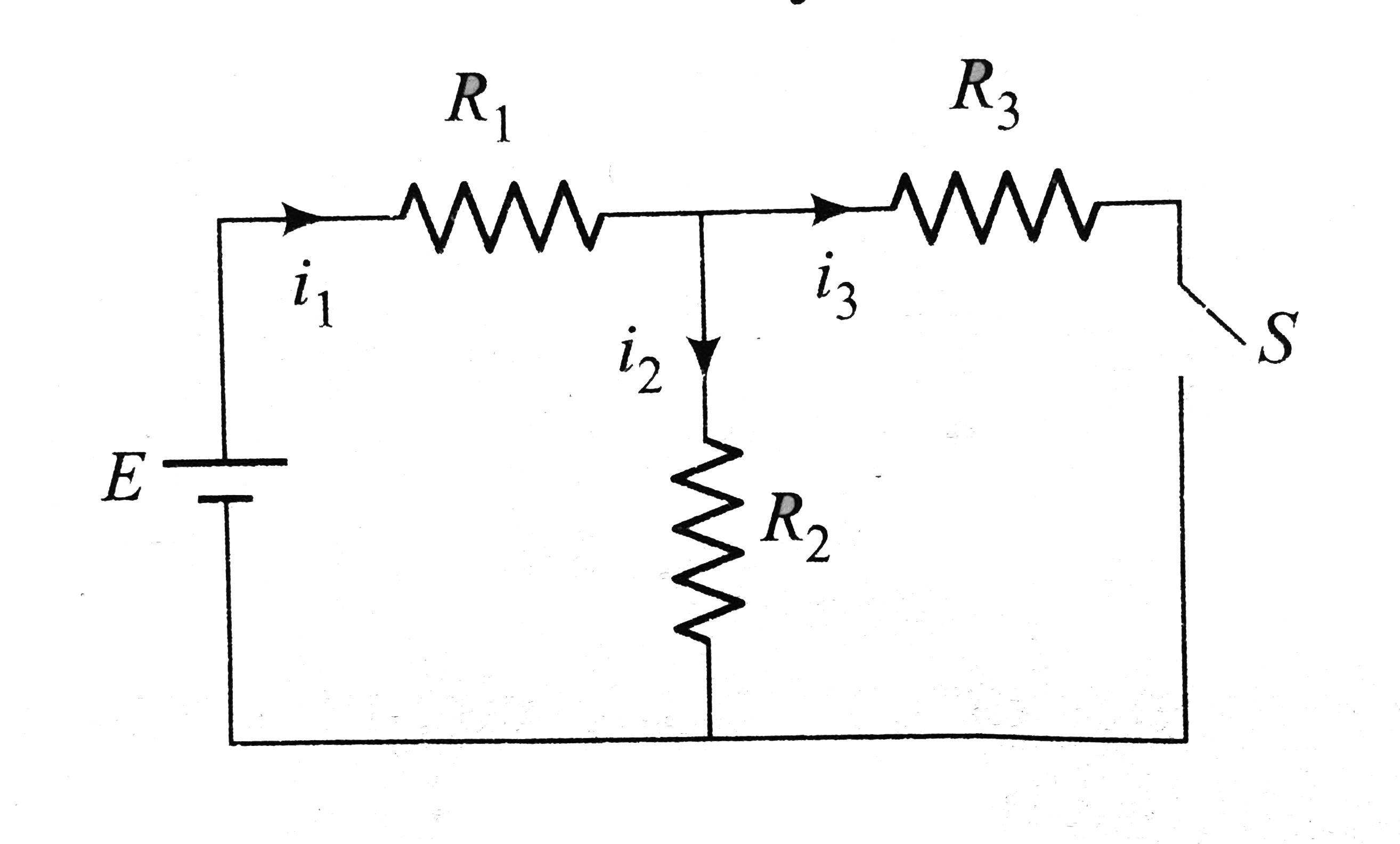
Immediately after tuning switch S on,
View Solution
