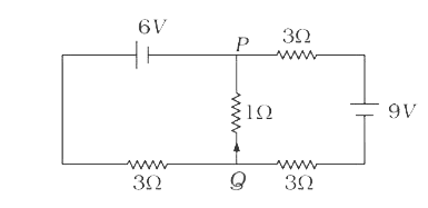
The diagram below shows part of a circuit:

If this arrangement of three resistors was to be replaced by a single resistors, its resistance should be:
9Ω
4Ω
6Ω
18Ω
The correct Answer is:A
Step by step video, text & image solution for The diagram below shows part of a circuit: If this arrangement of three resistors was to be replaced by a single resistors, its resistance should be: by Physics experts to help you in doubts & scoring excellent marks in Class 10 exams.
Topper's Solved these Questions
- BOOK - LAKHMIR SINGH & MANJIT KAURCHAPTER - ELECTRICITY EXERCISE - Very Short Answer Type Questions1videos
ELECTRICITY
- BOOK - LAKHMIR SINGH & MANJIT KAURCHAPTER - ELECTRICITY EXERCISE - Short Answer Type Questions2videos
ELECTRICITY
- BOOK - LAKHMIR SINGH & MANJIT KAURCHAPTER - ELECTRICITY EXERCISE - Sample Problem1videos
ELECTRICITY
- BOOK - LAKHMIR SINGH & MANJIT KAURCHAPTER - MAGNETIC EFFECT OF ELECTRIC CURRENT EXERCISE - NCERT BOOK2videos
MAGNETIC EFFECT OF ELECTRIC CURRENT
Similar Questions
Knowledge Check
- Question 1 - Select One
The figure below shows a colour-coded resistor. The resistance of this resistor is:
 A52×103±20%ΩB47×101±5%ΩC53×106±10%ΩD42±10%Ω
 - Question 2 - Select One
Which arrangement of 3Ω resistors will give a total resistance of 7Ω?
A B
B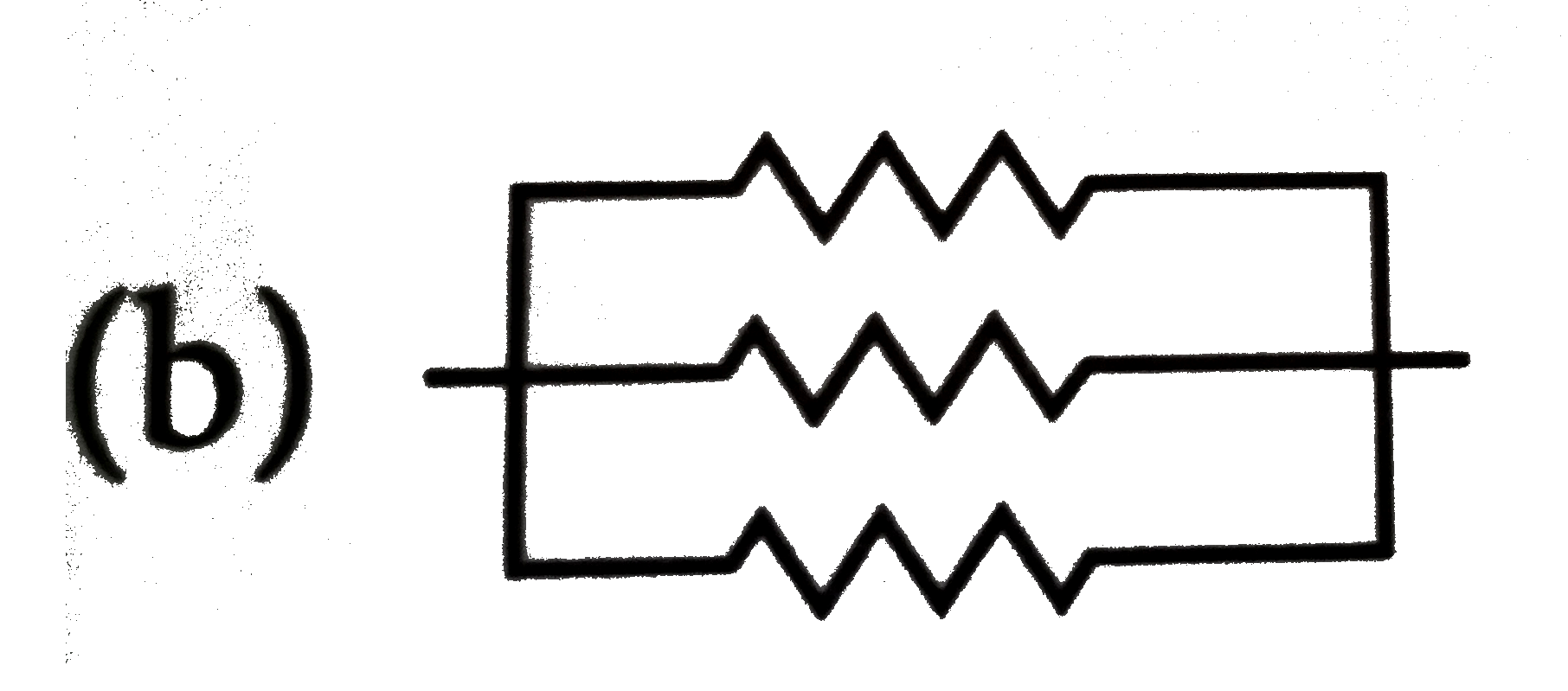 C
C D
D
- Question 3 - Select One
The part of a circuit shown in the figure consists of two ideal diodes and a few resistors. The equivalent resistance of the circuit between A and B is
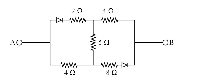 A4ΩB13ΩC4Ω or 13ΩD4Ω or zero
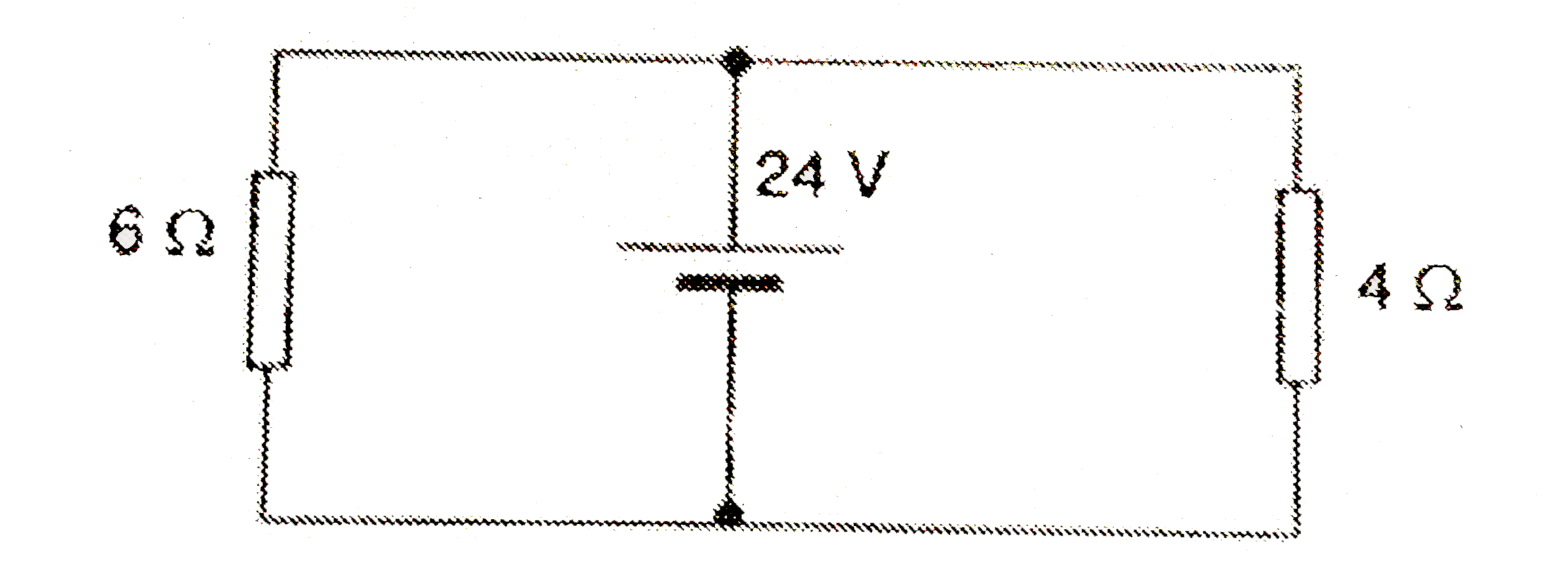
The figure given below shows an electric circuit in which current flows from a 6V battery through two resistors.

(a) Are the resistors connected in series with each other or in parallel?
(b) For each resistor, state the p.d. across it.
(c) The current flowing from the battery is shared between the two resistors. Which resistor will have bigger share of the current?
(d) Calculate the effective resistance of the two resistors.
(e) Calculate the current that flows from the battery.View SolutionThe figure given below shows three resistors:

Their combined resistane is:View SolutionThe current through the ammeter shown in figure is 1 A. If each of the 4Ω resistor is replaced by 2Ω resistor, the current in circuit will become nearly :
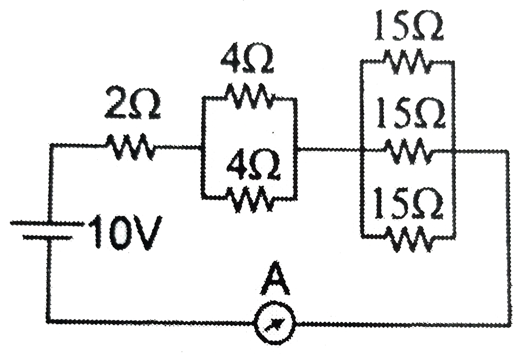 View Solution
Consider the circuit shown below. The current in the 4Ω resistor is
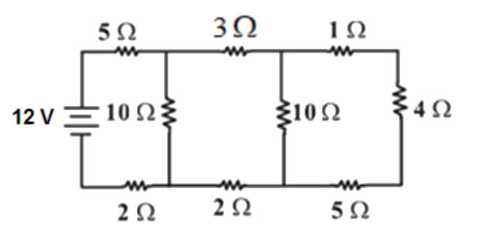 View Solution
There are mainly two types of combinations of resistors in a circuit, series and parallel. In the given table, Column I shows voltages of different arrangements of resistors, Column II shows different arrangement of resistors and Column III shows currents of different arrangements of resistors.
What are the conditions when resistor is in the parallel network?
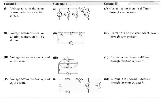 View Solution


