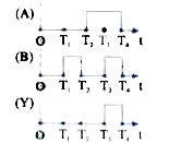
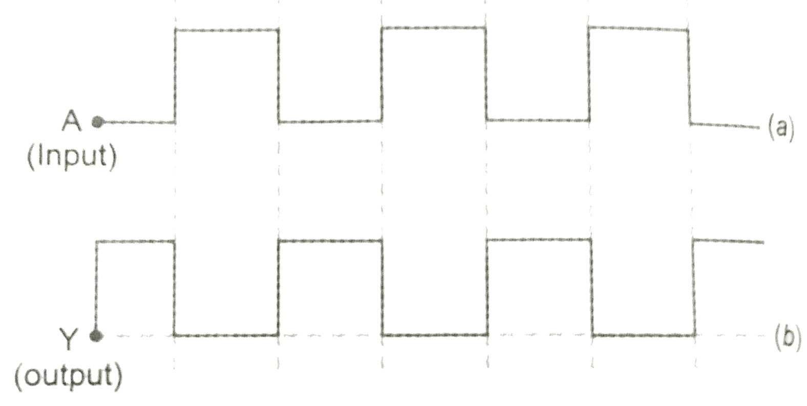
The input and the output wave form of a logic gate is shown in diagraam, then identify the logic gate :

A
AND gate
B
OR gate
C
NAND gate
D
NOT gate
Video Solution
Text Solution
The correct Answer is:A
|
Answer
Step by step video, text & image solution for The input and the output wave form of a logic gate is shown in diagraam, then identify the logic gate : by Physics experts to help you in doubts & scoring excellent marks in Class 12 exams.
Updated on:21/07/2023
Topper's Solved these Questions
- BOOK - NARAYNACHAPTER - SEMICONDUCTOR ELECTRONICSEXERCISE - C.U.Q (INTRINSIC AND EXTRINSIC SEMICONDUCTORS)70videos
SEMICONDUCTOR ELECTRONICS
- BOOK - NARAYNACHAPTER - SEMICONDUCTOR ELECTRONICSEXERCISE - C.U.Q (APPLICATION OF JUNCTION DIODE AS RECTIFIER)7videos
SEMICONDUCTOR ELECTRONICS
- BOOK - NARAYNACHAPTER - SEMICONDUCTOR ELECTRONICSEXERCISE - EVALUATE YOURSELF-35videos
SEMICONDUCTOR ELECTRONICS
- BOOK - NARAYNACHAPTER - SEMI CONDUCTOR DEVICESEXERCISE - Level-II (H.W)36videos
SEMI CONDUCTOR DEVICES
- BOOK - NARAYNACHAPTER - WAVE OPTICSEXERCISE - Exercise - 4 Polarisation9videos
WAVE OPTICS
Similar Questions
Knowledge Check
- Question 1 - Select One
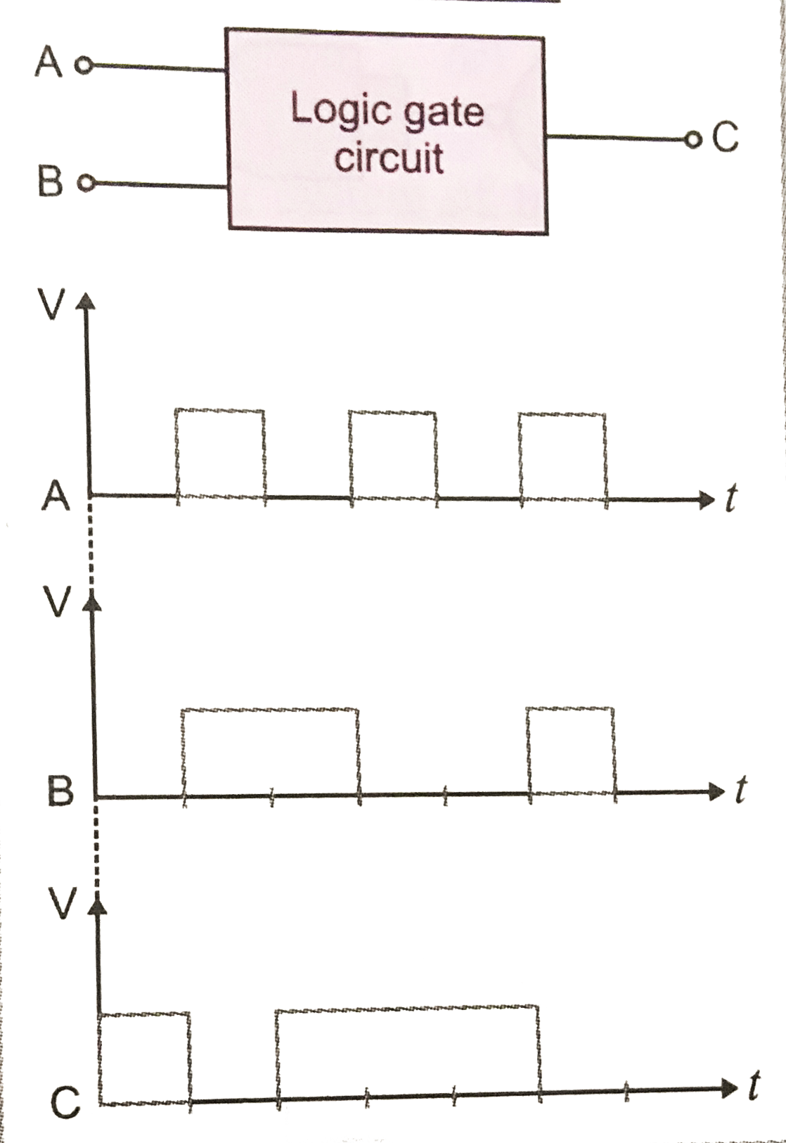
Fig, shows a logic gate circuit with two input A and B and the output C. The voltage wave form of A, B and C are as shown in Fig.The logic gate circuit is
 AOR gateBAND gateCNOR gateDNAND gate
 - Question 2 - Select One
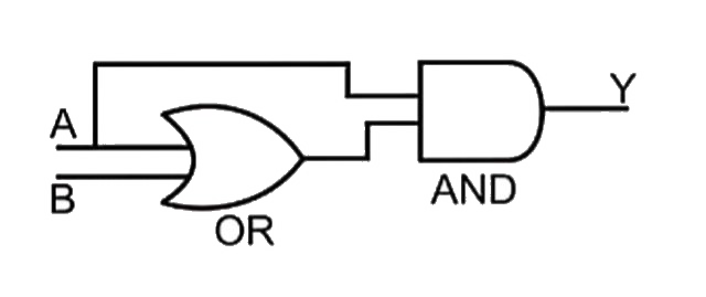
The output Y of the combination of logic gates shown is equal to
 AAB¯¯¯ACA+BDAB
Logic gates
View SolutionLogic gates
View SolutionLogic Gates
View SolutionLogic Gates
View SolutionUsing the wave forms of the input A and B, draw the output waveform of the given logic circuit . Identify the logic gate obtained . Write also the truth table.
 View Solution
The input wave form for NOT gate is shown in Fig.Draw the output wave form of this gate.
 View Solution

