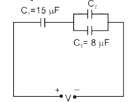
In the circuit shown in the figure, the total charge is 750μC and the voltage across capacitor C2 is 20 V. Then the charge on capacitor C2 is:
A
650μC
B
450μC
C
590μC
D
160μC
Video Solution
Text Solution
The correct Answer is:C
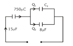
Q2=CV=8μf20=160μC
Q1=750−160=590μC
|
Updated on:21/07/2023
Topper's Solved these Questions
Similar Questions
Knowledge Check
- Question 1 - Select One
In the circuit shown in figure, the ratio of charge on 5μF and 2μF capacitor is
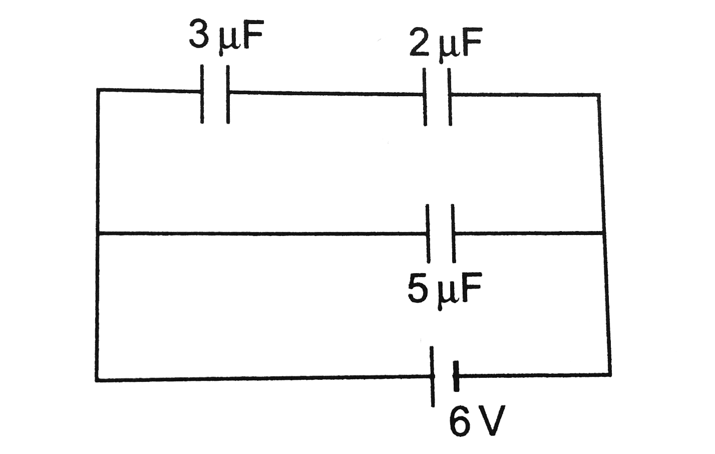 A54B53C38Dnone of these
 - Question 2 - Select One
In the circuit shown in the adjacent figure, the batteries are ideal. The charge on the capacitor C is
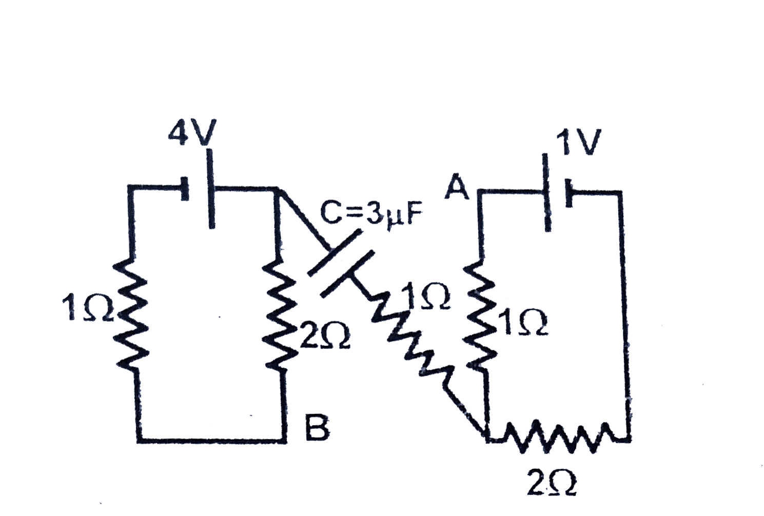 A10μCB20μCC30μCDzeo
 - Question 3 - Select One
The circuit is in a steady state.
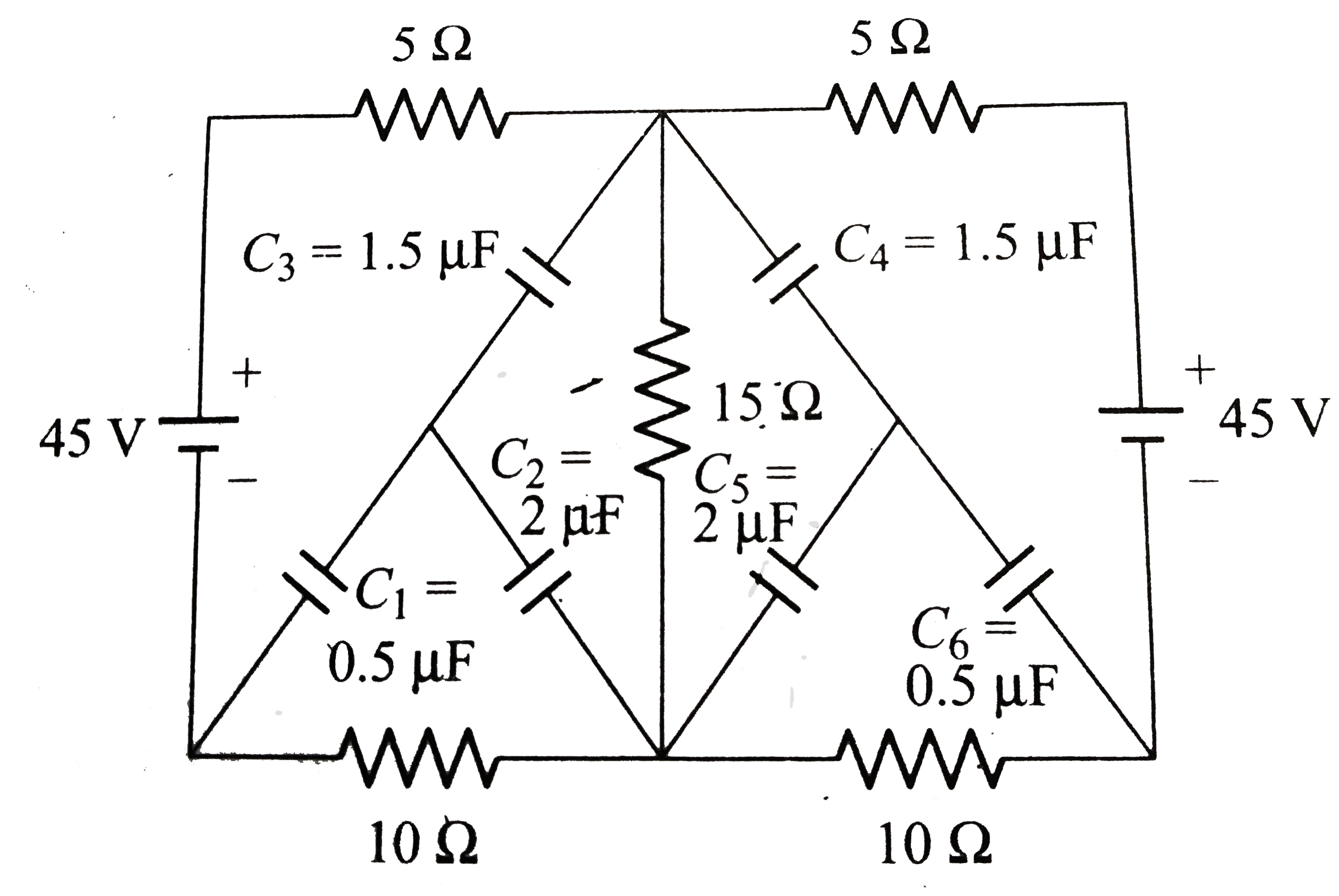
The charge in capacitor C2 isA30μCB10μCC20μCD40μC
For the circuit shown in figure the charge on 4μF capacitor is
 View Solution
In the circuit shown , charge on the 5μF capacitor is :
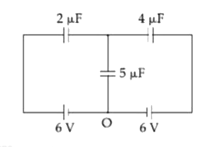 View Solution
The voltage applied across a capacitor having a capacitance of 10μF is varies as shown in figure:
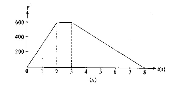
At the time instant when the terminal voltage across capacitor is 600V calculate
(a) The charge on capacitor ltBrgt (b) The energy stored in the capacitor
(c) Draw the curve of current in connecting wires as a function of time.View SolutionIn the circuit shown in figure. Charge stored in 6μF capacitor will be
 View Solution
In the circuit shown in figure, the final voltage drop across the capacitor C is :
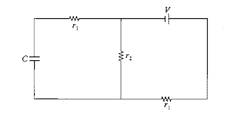 View Solution


