A combination arrangement of the capacitors is shown in the figure
(ii) If a potential difference of 48 V is applied across points a and b, then charge on the capacitor C3 at steady state condition will be :
A
8μC
B
16μC
C
32μC
D
64μC
Text Solution
The correct Answer is:D
|
Topper's Solved these Questions
- CAPACITANCEBOOK - RESONANCECHAPTER - CAPACITANCEEXERCISE - Exercise - 3
26 Videos
- CAPACITANCEBOOK - RESONANCECHAPTER - CAPACITANCEEXERCISE - High Level Problems
16 Videos
- CAPACITANCEBOOK - RESONANCECHAPTER - CAPACITANCEEXERCISE - Exercise - 1
79 Videos
- ATOMIC PHYSICSBOOK - RESONANCECHAPTER - ATOMIC PHYSICSEXERCISE - Advanved level problems
17 Videos
- COMMUNICATION SYSTEMSBOOK - RESONANCECHAPTER - COMMUNICATION SYSTEMSEXERCISE - Exercise 3
13 Videos
Similar Questions
Knowledge Check
The charge on the capacitor in steady state in the circuit shown is
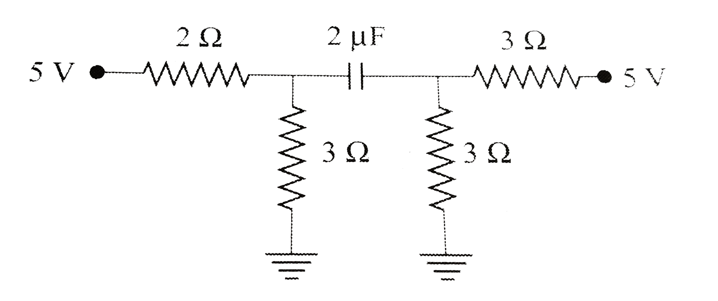 A0.5μCB1μCC2μCD4μC
The circuit is in a steady state.
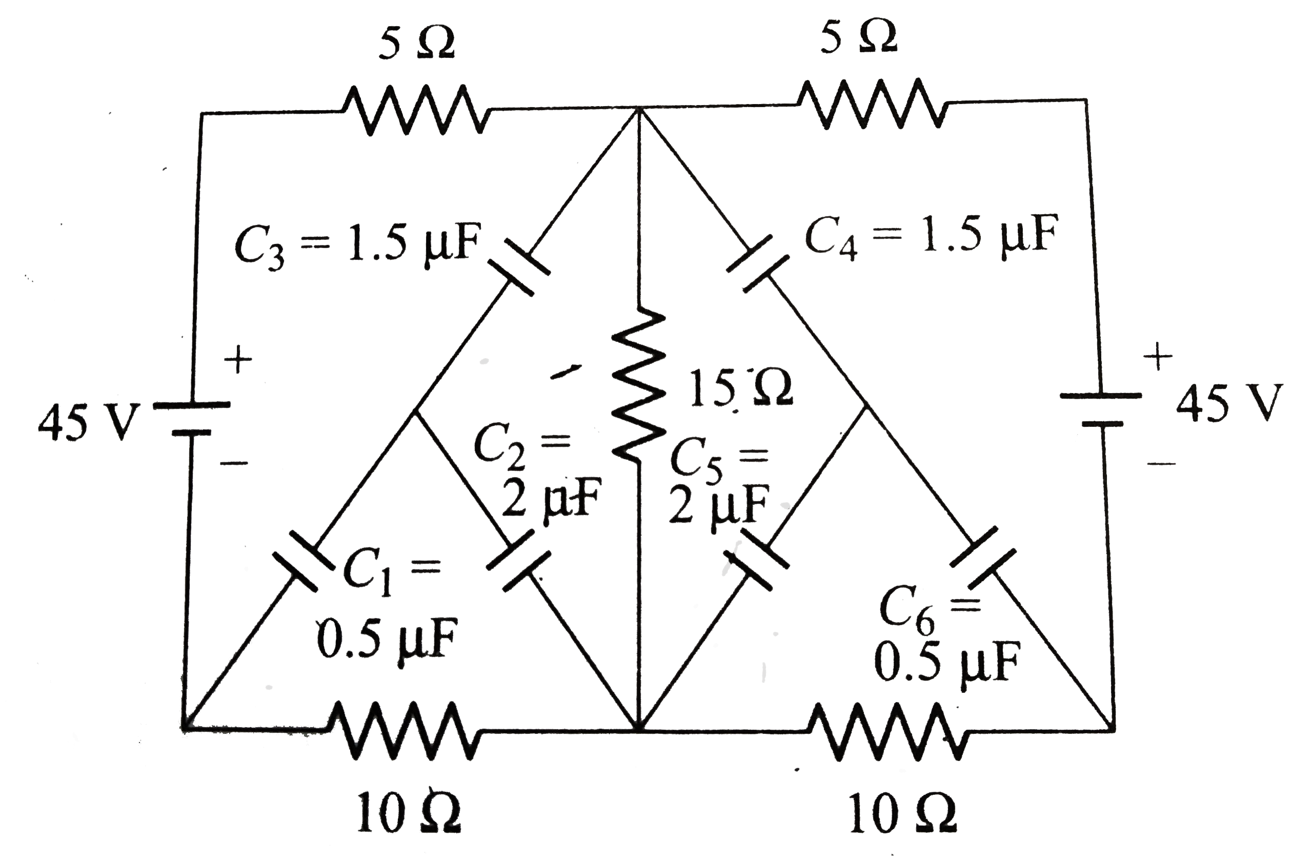
The charge in capacitor C3 isA10μCB30μCC20μCD40μC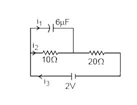
In steady state, find the charge on the capacitor shown in figure.A4μCB5μCC6μCD7μC
In the circuit shown in figure find the charges on the three capacitors in steady state.
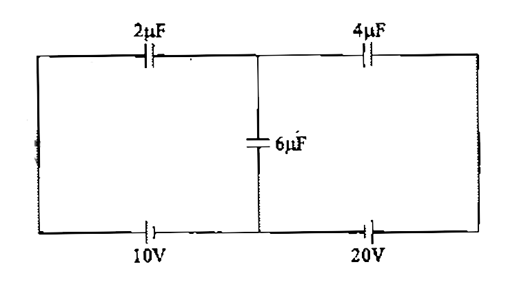
View SolutionA potential difference of 250 Volt is applied across the plate of a capacitor of 10 pF. Calculate the charge on the plates of the capacitor.
View SolutionThe charge on the capacitor of capacitance 10μF in steady state condition in the circuit shown is
_PHY_E05_271_Q01.png)
View SolutionFor the circuit shown in the figure determine the charge on capacitor in steady state.
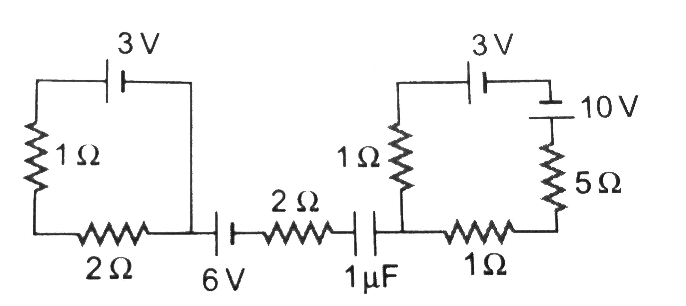
View SolutionFor the circuit shown in the figure determine the charge on capacitor in steady state.

View Solution
