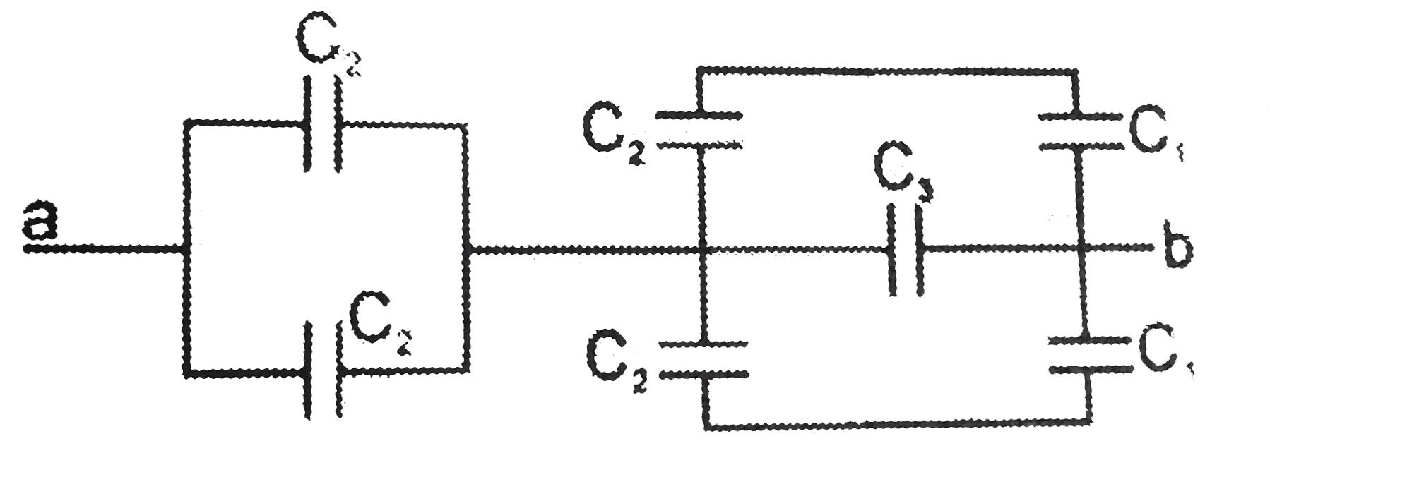
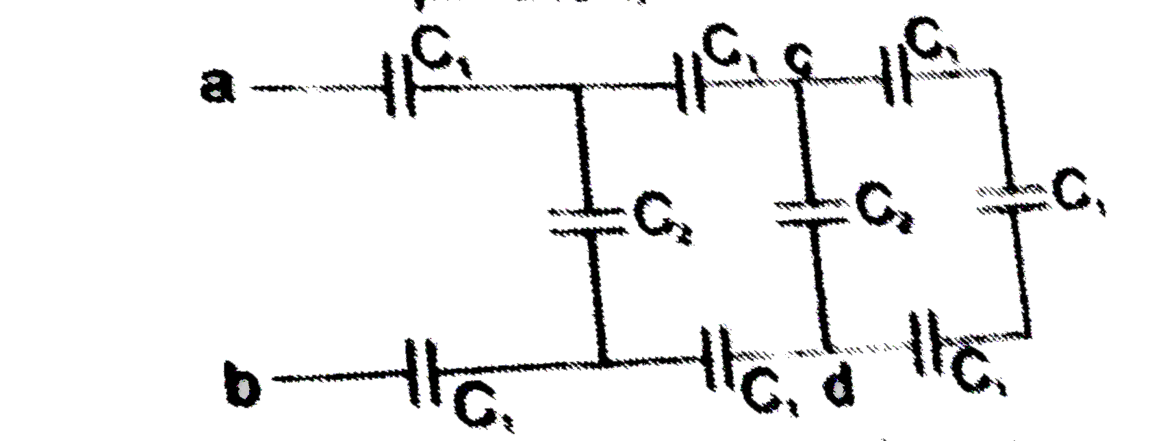
A combination arrangement of the capacitors is shown in the figure
(i) C1=3μF,C2=6μF and C3=2μF then equivalent capacitance between 'a' and 'b' is :
4μF
6μF
1μF
2μF
The correct Answer is:A
Step by step video, text & image solution for A combination arrangement of the capacitors is shown in the figure (i) C_(1)=3 mu F, C_(2) =6 mu F and C_(3)= 2 mu F then equivalent capacitance between 'a' and 'b' is : by Physics experts to help you in doubts & scoring excellent marks in Class 12 exams.
Topper's Solved these Questions
- BOOK - RESONANCECHAPTER - CAPACITANCEEXERCISE - Exercise - 326videos
CAPACITANCE
- BOOK - RESONANCECHAPTER - CAPACITANCEEXERCISE - High Level Problems16videos
CAPACITANCE
- BOOK - RESONANCECHAPTER - CAPACITANCEEXERCISE - Exercise - 179videos
CAPACITANCE
- BOOK - RESONANCECHAPTER - ATOMIC PHYSICSEXERCISE - Advanved level problems17videos
ATOMIC PHYSICS
- BOOK - RESONANCECHAPTER - COMMUNICATION SYSTEMSEXERCISE - Exercise 313videos
COMMUNICATION SYSTEMS
Similar Questions
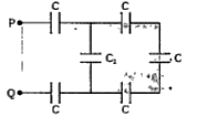
Find the equivalent capacitance between P and Q if C1=6μFandC=9μF
 View Solution
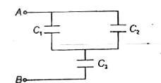
(a ) Find the equivalent capacitance of the combination shown in the figure ( a) when C1=2.0μF,C2=4.0μF and C3=3.0μF
(b ) The input terminals A and B in figure (a) are connected to a battery of 12 V. Find the potential and the charge of each capacitor .View Solution
Knowledge Check
- Question 1 - Select One
In the arrangement C1=10μ,FC2=10μF and C3=20μF . What is the equivalent capacitance ( in μF ) between points A and B ?
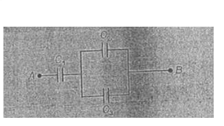 A7.5B10C12D15
 - Question 2 - Select One
In the arrangement of the capacitor shown in the figure, each C1 capacitor has capacitance of 3μF and each C2 capacitor has capacitance of 2μF then,
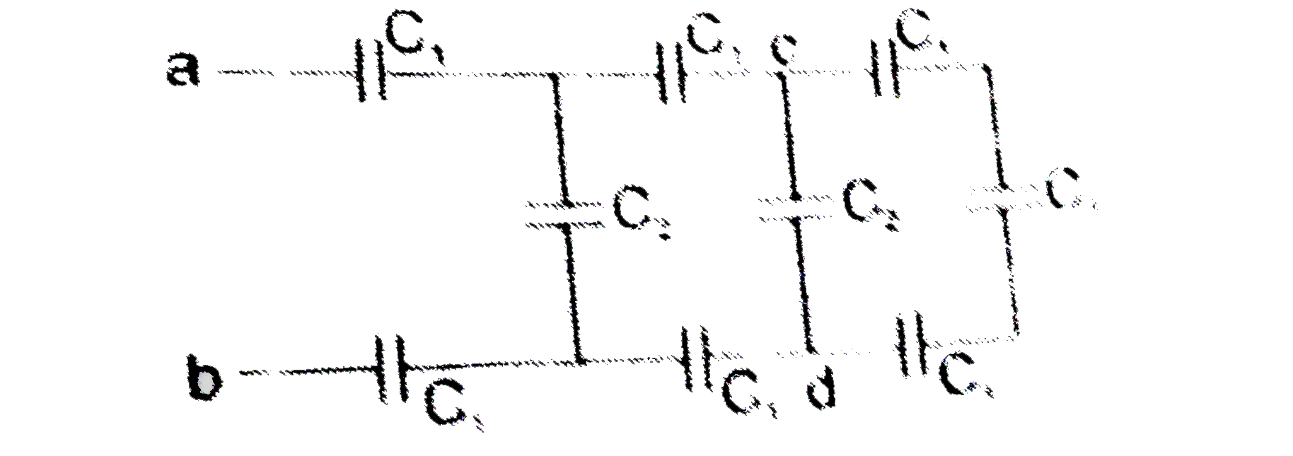
(i) Equivalent capacitance of the network between the points a and b is :A1μFB2μFC4μFD32μF - Question 3 - Select One
In the arrangement of the capacitor shown in the figure, each C1 capacitor has capacitance of 3μF and each C2 capacitor has capacitance of 2μF then,
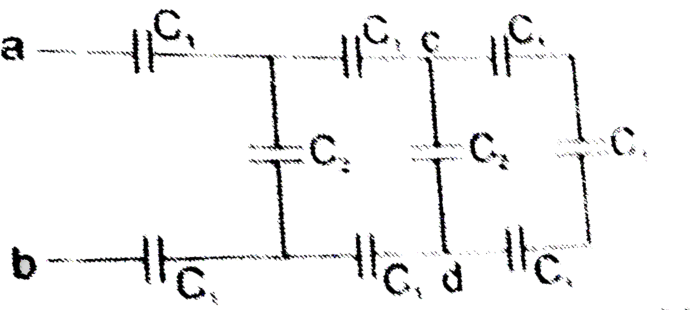
(ii) If Vab=900V, the charge on each capacitor nearest to the points 'a' and 'b' is :A300μCB600μCC450μCD900μC
In the circuit shown the capacitors areC1=15μF,C2=10μFandC2=25μF.Find
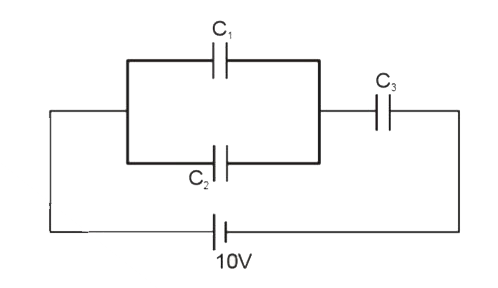
(i) The equivalent capacitance of the circuit
(ii) The charge on each capacitor and
(iii) The potential difference a across each capacitor.View SolutionIn fig, the values of capacitances are as follow
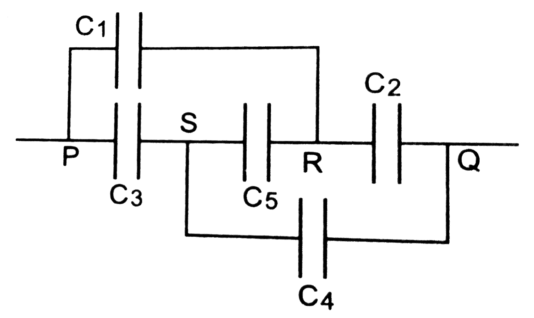
C1=C2=C3=C4=4μF,C5=5μF Calculate the equivalent capacitance between the points P and Q. If a battery of 10 volt is connected between these points, what will be the charge on each capacitor ?
 View Solution
An infinite ladder network consisting of all equal resistances, r=102.732Ω is placed side by side to a capacitor system as shown in fig. Initially, all the switches are kept open and all the three capacitors are given equal charges of 30μCeach. The capacitances are C1=3μF,C2=6μFandC3=6μF. Polarity of charges on the capacitor plates is shown in the fig. Now all the three switches are closed simultaneously.
(a) find the magnitude of rate of change of charge on the plates of the capacitors immediately after the switches are closed.
(b) Calculate heat generated in the circuit by the time steady sate condition is established.
 View Solution
In the arrangement of the capacitor shown in the figure, each C1 capacitor has capacitance of 3μF and each C2 capacitor has capacitance of 2μF then,
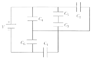
(iii) If Vab=900V, then potential difference across points c and d is :View SolutionWhat is the equivalent capacitance of the capacitors in the following figure?
Given that C1=C6=3μFandC3=C5=2C2=2C4=4μF
 View Solution

