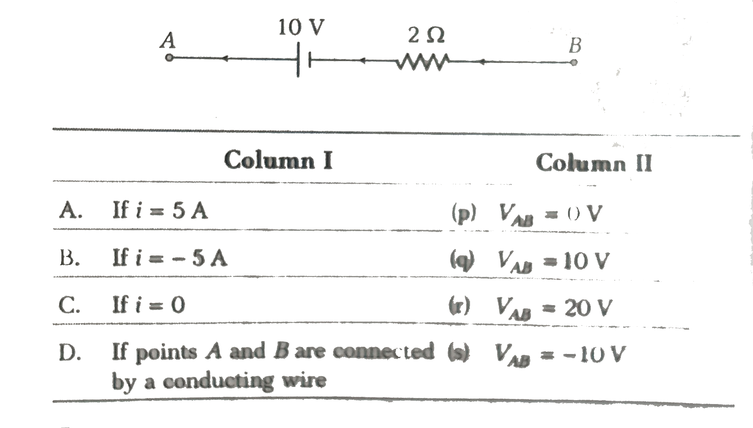
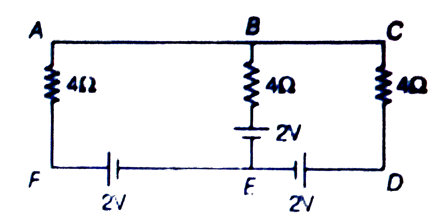
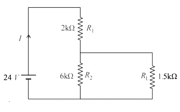
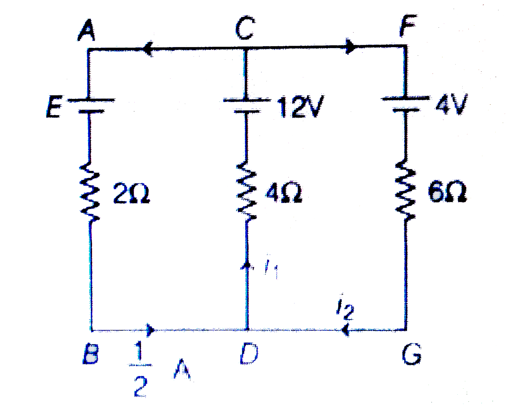
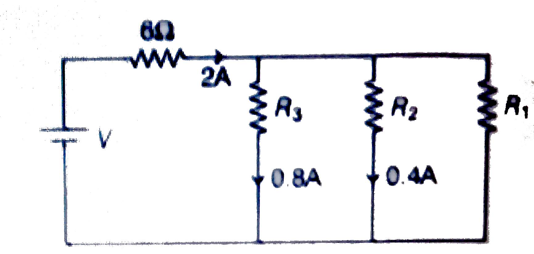
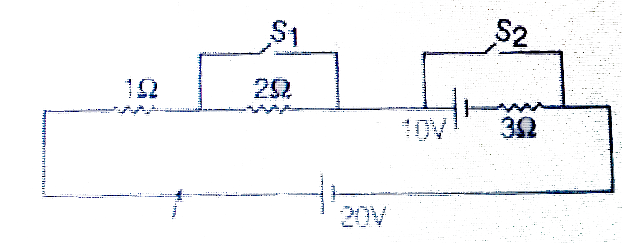
In the part of circuit shown in figure-3.364

A
current will flow form A to B
B
current may flow from A to B
C
current will flow B to A
D
the direction of curent will depend on r.
Video Solution
Text Solution
The correct Answer is:B
|
Answer
Step by step video, text & image solution for In the part of circuit shown in figure-3.364 by Physics experts to help you in doubts & scoring excellent marks in Class 12 exams.
Updated on:21/07/2023
Topper's Solved these Questions
- BOOK - RESONANCECHAPTER - CURRENT ELECTRICITYEXERCISE - Exercise-1 (Part-3)2videos
CURRENT ELECTRICITY
- BOOK - RESONANCECHAPTER - CURRENT ELECTRICITYEXERCISE - Exercise-2 (Part-1)25videos
CURRENT ELECTRICITY
- BOOK - RESONANCECHAPTER - CURRENT ELECTRICITYEXERCISE - Exercise-1 (Part-1)46videos
CURRENT ELECTRICITY
- BOOK - RESONANCECHAPTER - COMMUNICATION SYSTEMSEXERCISE - Exercise 313videos
COMMUNICATION SYSTEMS
- BOOK - RESONANCECHAPTER - DAILY PRACTICE PROBLEMEXERCISE - DPP.No.711videos
DAILY PRACTICE PROBLEM
Similar Questions
Knowledge Check
- Question 1 - Select One
In the part of a circuit shown in figure, the potential different
(VG−VH) between points G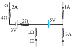 A0VB15VC21VD3V
 - Question 2 - Select One
In the two circuits shown in figure
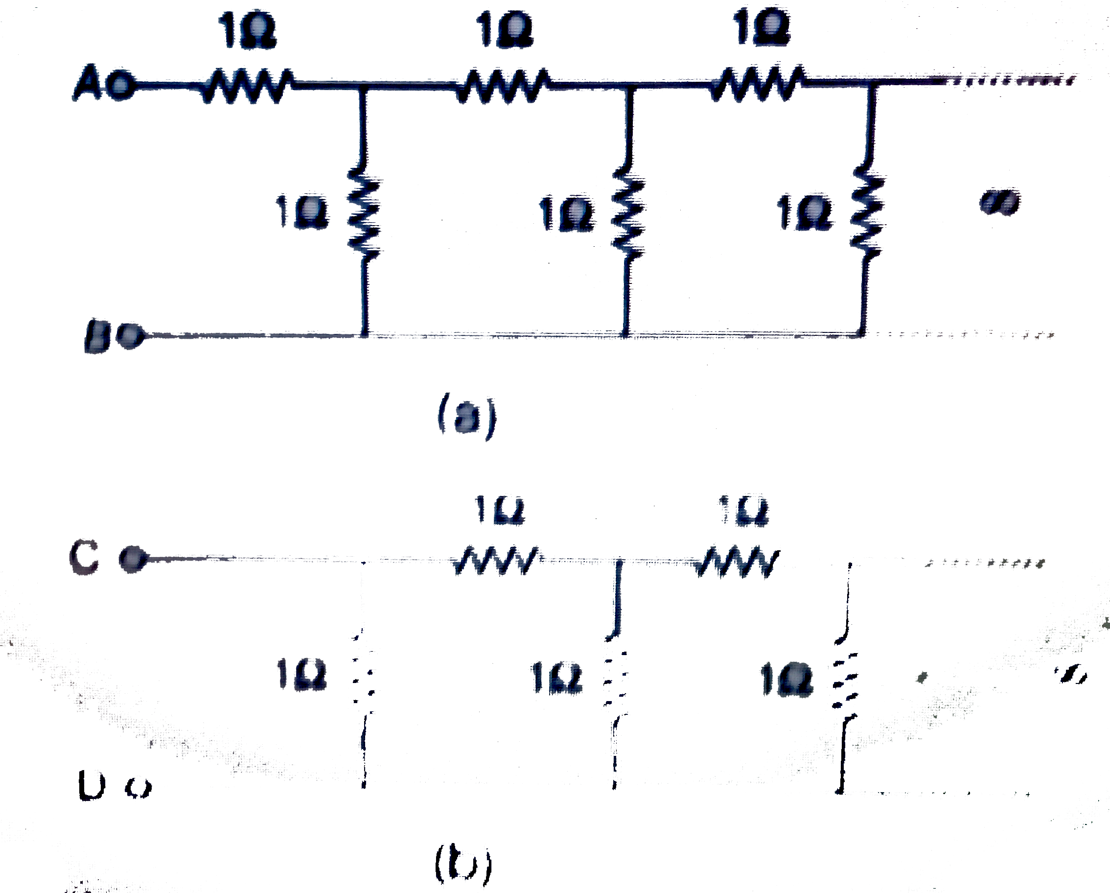 ARAB=RCD=(√3+2)ΩBRAB=(√3+1)ΩCRCD=(√5+1)ΩDRAB>RCD
 - Question 3 - Select One or More
Assertion: In the part of the circuit shown in figure, maximum power is produced across R.
Reason : Power P=V2R
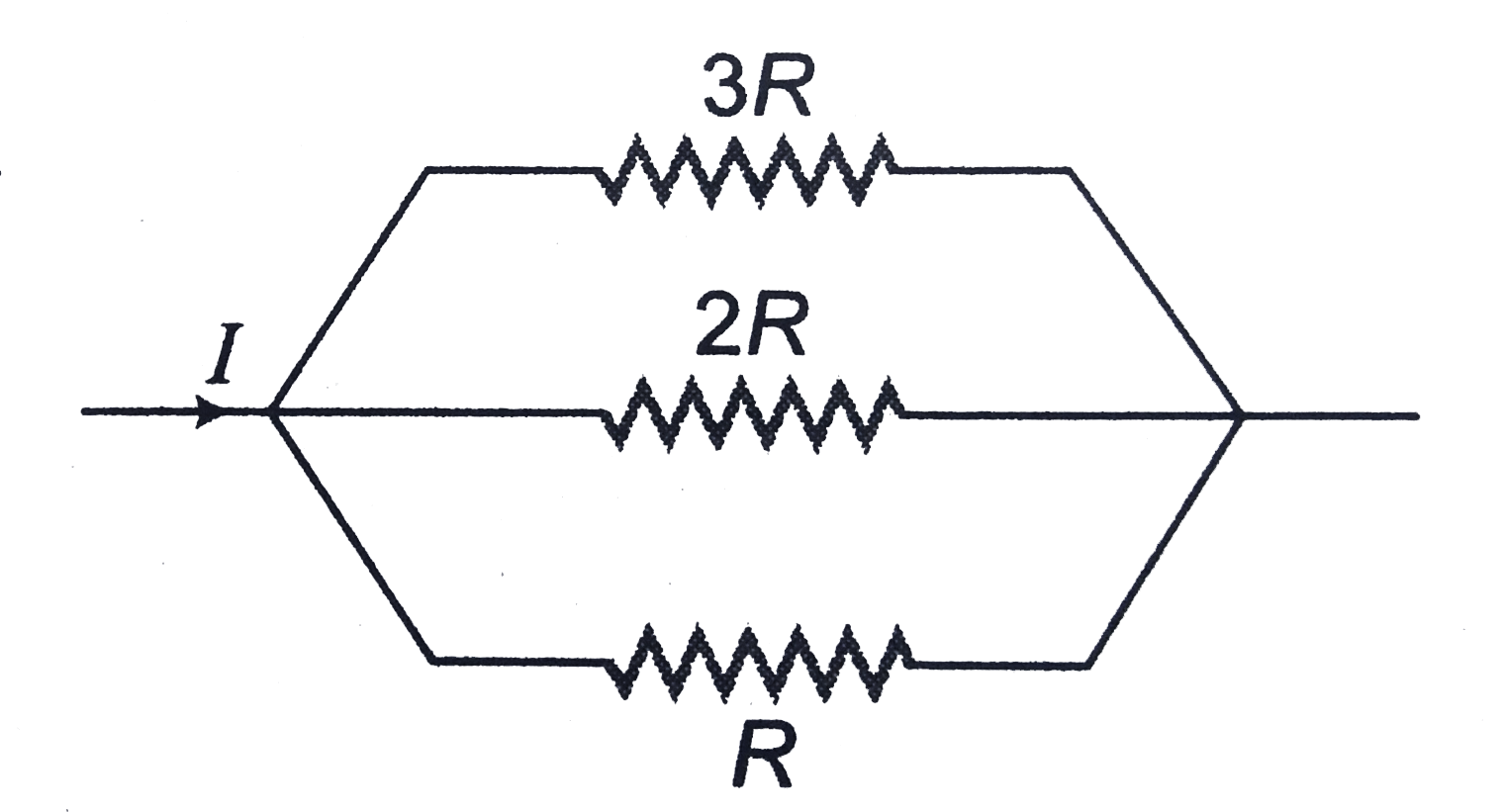 AIf both Assertion and Reason are true and the Reason is correct explanation of the Assertion.BIf both Assertion and Reason are true but Reason is not the correct explanation of Assertion.CIf Assertion is true, but the Reason is false.DIf Assertion is false but the Reason is true.


