In the circuit shown all the resistors are of same resistance R=11Ω and C=2μF. They are connected through a battery of 10 V. When the cell is switched on, find
(a) maximum current in the circuit, and
(b) energy stored in the capacitor after time t
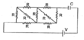
0.666A,12CV2(1−e−t/RC)2
Topper's Solved these Questions
- CURRENT ELECTRICITYBOOK - FIITJEECHAPTER - CURRENT ELECTRICITYEXERCISE - ASSIGNMENT PROBLEMS (OBJECTIVE)(Level-1)
45 Videos
- CURRENT ELECTRICITYBOOK - FIITJEECHAPTER - CURRENT ELECTRICITYEXERCISE - ASSIGNMENT PROBLEMS (OBJECTIVE)(Level-II)
20 Videos
- CURRENT ELECTRICITYBOOK - FIITJEECHAPTER - CURRENT ELECTRICITYEXERCISE - ASSIGNMENT PROBLEMS (SUBJECTIVE)(Level-1)
15 Videos
- COLLISION BOOK - FIITJEECHAPTER - COLLISION EXERCISE - (NUMERICAL BASED QUESTIONS)
4 Videos
- ELASTICITY AND WAVES BOOK - FIITJEECHAPTER - ELASTICITY AND WAVES EXERCISE - Assignment Problems (Objective) Level-II
15 Videos
Similar Questions
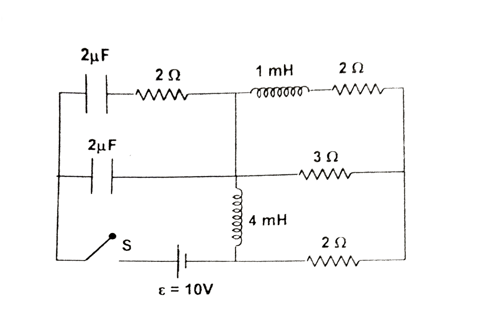
In the circuit shown, all the capacitors are initially uncharged. The current through the battery just after closing the switch 'S' is
View SolutionA capacitor of 2.0μF is connected to a battery of 2V through a resistance of 10kΩ. Calculate (i) the initial current in the circuit and (ii) the current after 0.02s.
View Solution
Knowledge Check

In the circuit shown, all the capacitors are initially uncharged. The current through the battery just after closing the switch 'S' isA2AB4AC5AD10AIn a series circuit C=2μF,L=1mH and R=10Ω, when the current in the circuit is maximum, at that time the ratio of the energies stored in the capacitor and the inductor will be
A1:1B1:2C2:1D1:5The circuit consists of two resistors (of resistance R1=20Ω and R2=10Ω), a capacitor (of capacitance C=10μF) and two ideal cells. In the circuit shown the capacitor is in steady state and the switch S is open
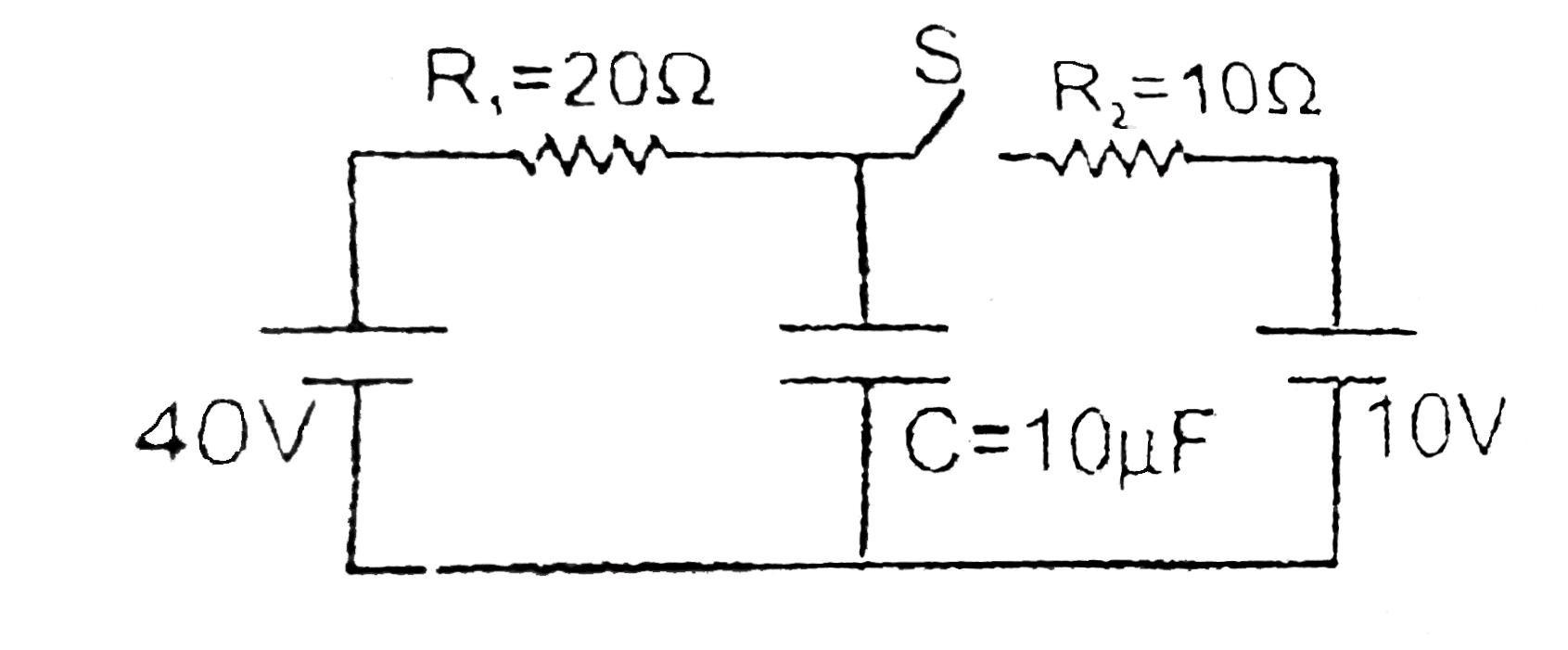
The charge on capacitor in steady state with switch S closed.A100μCB200μCC300μCD400μC
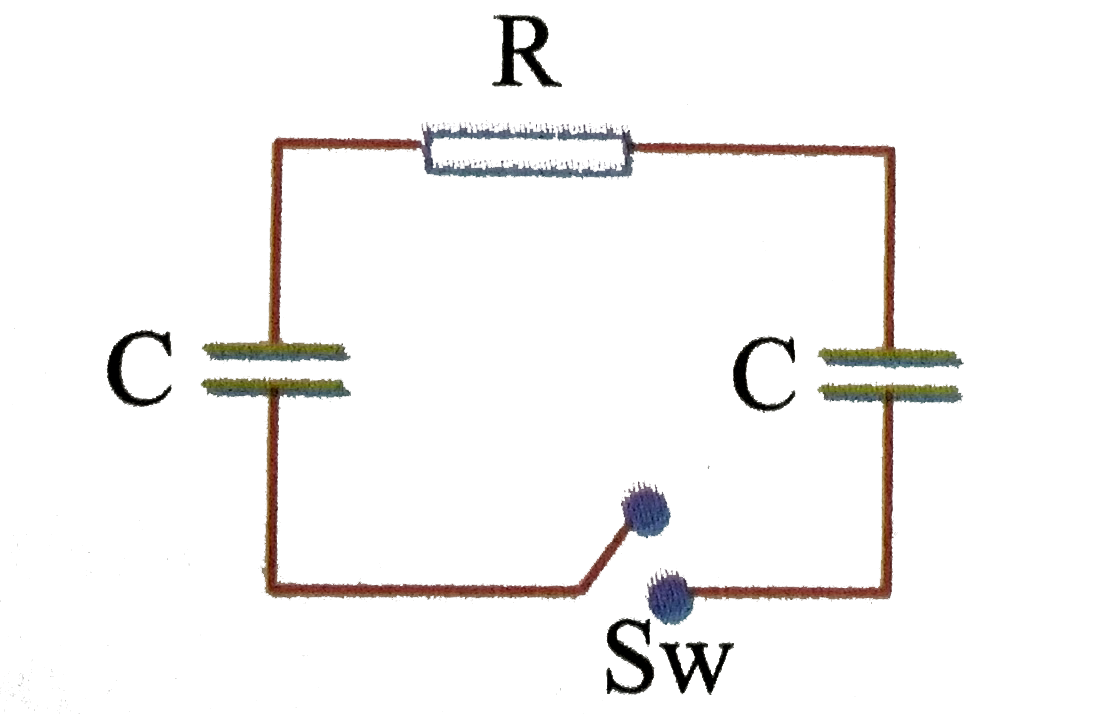
In the circuit shown, a capacitor charged to a potential difference V0 is connected to an uncharged capacitor through a resistor at t=0, by closing the switch. Find current in the circuit as function of time.
 .
.
View SolutionIn the circuit diagram given below, three resistors R1,R2, and R3 of 5Ω,10Ω and 30Ω, respectively are connected as shown.
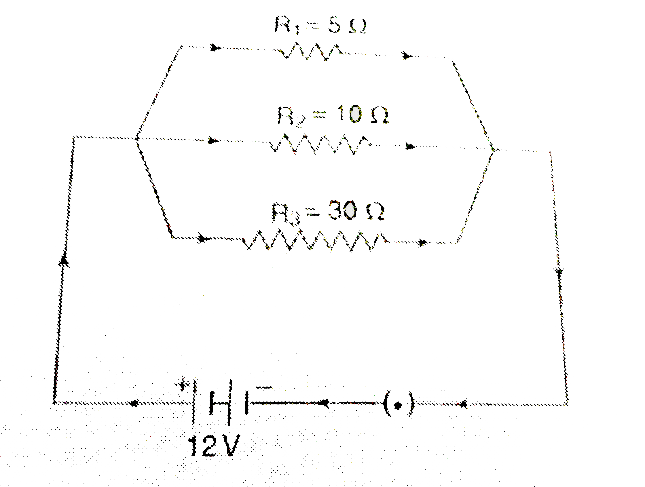
Calculate:
(a) current through each resistor.
(b) total current in the circuit.
(c) total resistance in the circuit.
View SolutionIn the circuit diagram given below, three resistors R1,R2, and R3 of 5Ω,10Ω and 30Ω, respectively are connected as shown.

Calculate:
(a) current through each resistor.
(b) total current in the circuit.
(c) total resistance in the circuit.
View SolutionThe circuit diagram in Fig. shows three resistors 2Ω,4Ωand RΩ connected to a battery of e.m.f. 2 V and internal resistance 3 Ω. If current of 0.25 A flows through the circuit, find :
the p.d. across the R Ωor 2 Ω resistor,
View SolutionThe circuit diagram in Fig. shows three resistors 2Ω,4Ωand RΩ connected to a battery of e.m.f. 2 V and internal resistance 3 Ω. If current of 0.25 A flows through the circuit, find :
the p.d. across the internal resistance of the cell,
View Solution
