A rigid wire loop of square shape having side of length L and resistance R is moving along the X-axis with a constant velocity v0 in the plane of the paper. At t = 0, the right edge of the loop enters a region of length 3L where there is a uniform magnetic field B0 into the plane of the paper, as shown in the figure. For sufficiently large V0, the loop eventually crosses the region. Let x be the location of the right edge of the loop. Let U(x), I(x), and F(x) represent the velocity of the loop, current in the loop, and force on the loop, respectively, as a function of x. Counter-clockwise current is taken as positive.

Which of the following schematic plot(s) is(are) correct? (Ignore gravity)


The correct Answer is:A, B
Net emf is induced in the loop only when 0<x<L, hence when loop is entering into the field.
Similarly emf is induced when loop is exiting the magnetic field hence when 3L<x<4L.
Let us first understand the situation when loop is entering into the field. 0<x<L
Let v be the instantaneous velocity of the loop in this interval of x. Induced emf will be Bvl and current flowing will be anticlockwise to oppose increasing magnetic flux. Anticlockwise direction is assumed to be positive and hence, option (c) is wrong. Because initial current is shown to be negative in this graph, Here one more point can be noted that magnetic force acting on the loop has to be in negative direction of X-axis to oppose the entering loop and hence, option (d) is also wrong because force shown is positive. Now we need to check option (a) and (b) only. Induced emf is Bvl and resistance of the circuit is R and hence current flowing in the loop is
I=BvL/R
−mdvdt=ILB
−mdvdtdxdt=B2L2vR
−mdvdtv=B2L2vR
dv=−B2L2mRdx
∫vv0dv=−B2L2mR∫x0dx
v−v0=−B2L2mRx
v=v0−B2L2mRx
We can see that variation in velocity is linear with negative slope. When loop fully enters the magnetic field then force stops acting and velocity is maintained and when the loop exits the magnetic tield then also magnetic force acts in the same way to decrease the velocity linearly. Hence, option (a) is correct. Curent flowing in the loop is given by the following equation:
I=BvL/R
Hence variation in current is also linear. But when loop is fully inside the magnetic field then current stops flowing in the loop. But when loop exits the magnetic field then current again changes linearly but in opposite direction. Hence, option (b) is correct. Hence, options (a) and (b) are correct.
Topper's Solved these Questions
- ELECTROMAGNETIC INDUCTIONBOOK - MODERN PUBLICATIONCHAPTER - ELECTROMAGNETIC INDUCTIONEXERCISE - COMPETITION FILE (MULTIPLE CHOICE QUESTIONS BASED ON GIVEN PASSAGE)
7 Videos
- ELECTROMAGNETIC INDUCTIONBOOK - MODERN PUBLICATIONCHAPTER - ELECTROMAGNETIC INDUCTIONEXERCISE - COMPETITION FILE (ASSERTION REASON TYPE QUESTIONS)
10 Videos
- ELECTROMAGNETIC INDUCTIONBOOK - MODERN PUBLICATIONCHAPTER - ELECTROMAGNETIC INDUCTIONEXERCISE - COMPETITION FILE (MULTIPLE CHOICE QUESTIONS) (AIPMT/NEET & Other State Boards for Medical Entrance)
8 Videos
- ELECTRIC CHARGES AND FIELDS BOOK - MODERN PUBLICATIONCHAPTER - ELECTRIC CHARGES AND FIELDS EXERCISE - Chapter Practice Test
15 Videos
- ELECTROMAGNETIC WAVESBOOK - MODERN PUBLICATIONCHAPTER - ELECTROMAGNETIC WAVESEXERCISE - CHAPTER PRACTICE TEST
14 Videos
Similar Questions
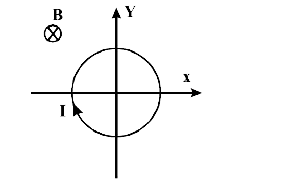
A conducting loop carrying a current I is placed in a uniform magnetic field ponting into the plane of the paper as shown. The loop will have a tendency to
View SolutionThere is a uniform magnetic field directed perpendicular and into the plane of the paper. An irregular shaped conducting loop is slowly changing into a circular loop in the plane of the paper. Then
View Solution
Knowledge Check
A conducting loop carrying a current I is placed in a uniform magnetic field ponting into the plane of the paper as shown. The loop will have a tendency to
 AcontractBexpandCmove towards +vex−aξsDmove towards −vex−aξs
There is a uniform magnetic field directed perpendicular and into the plane of the paper. An irregular shaped conducting loop is slowly changing into a circular loop in the plane of the paper. Then
Acurrent is induced in the loop in the anticlockwise directionBcurrent is induced in the loop in the clockwise directionCAltrenating current is induced in the loopDno current is induced in the loopThere is a uniform magnetic field directed perpendicular and into the plane of the paper. An irregular shaped conducting loop is slowly changing into a circular loop in the plane of the paper. Then
Acurrent is induced in the loop in the anti-clockwise directionBcurrnet is induced in the loop in the clockwise direction.Cac is induced in the loop.Dno current is induced in the loop.
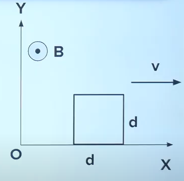
A square loop of side d is moved with velocity vˆi in an non-uniform magnetic field B0axˆk then the emf induced shown is?
View SolutionA conducting rod AC of length 4l is rotated about point O in a uniform magnetic field →B directed into the plane of the paper. AO=landOC=3l. Find VA−VC.
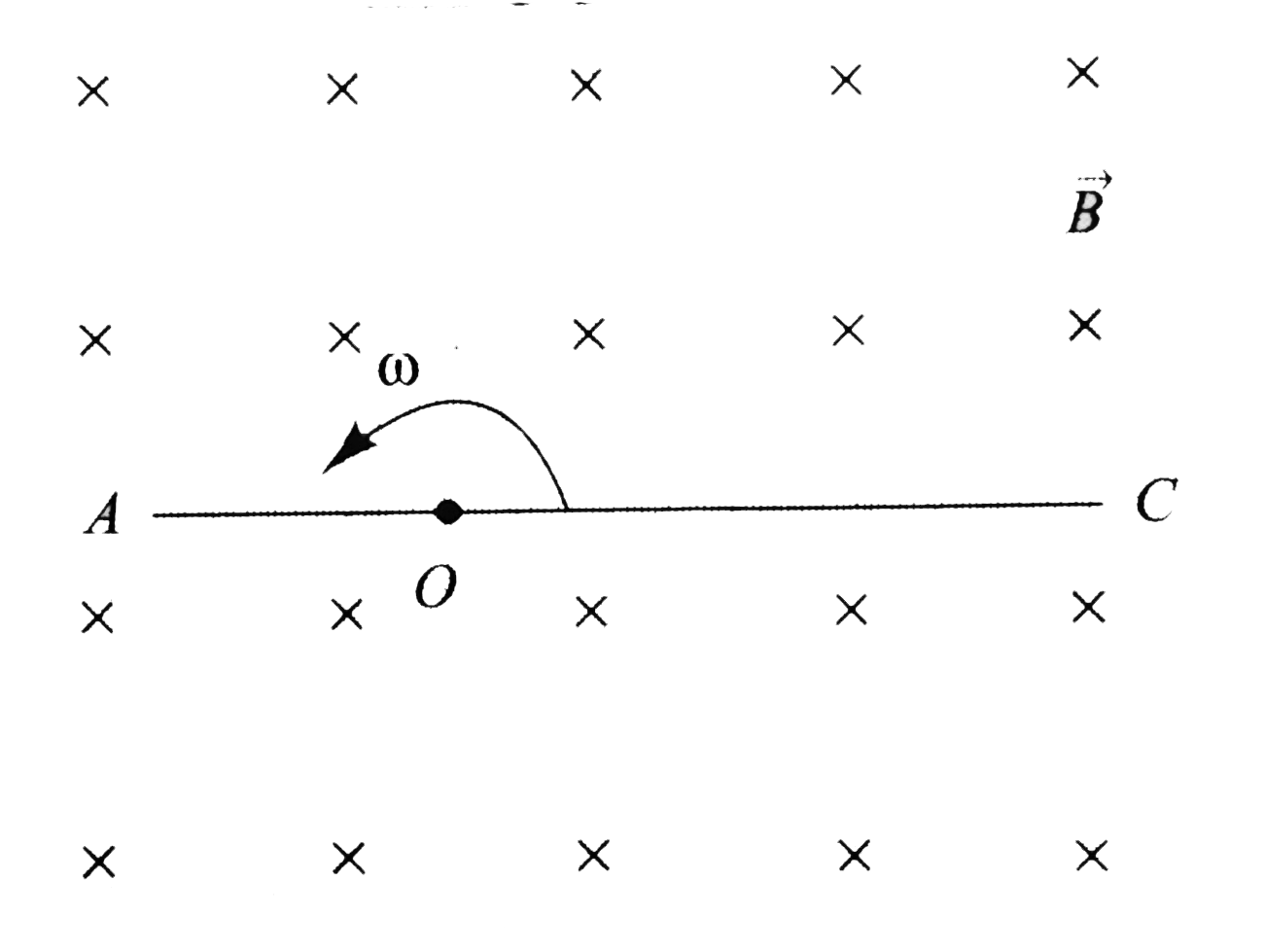
View SolutionA conducting rod AC of length 4l is rotated about point O in a uniform magnetic field →B directed into the plane of the paper. AO=landOC=3l. Find VA−VC.

View SolutionAn equilateral triangular loop ADC having some resistance is pulled with a constant velocity v out of a uniform magnetic field directed in to the paper. At time t=0, side DC of the loop at is at edge of the magnetic field.
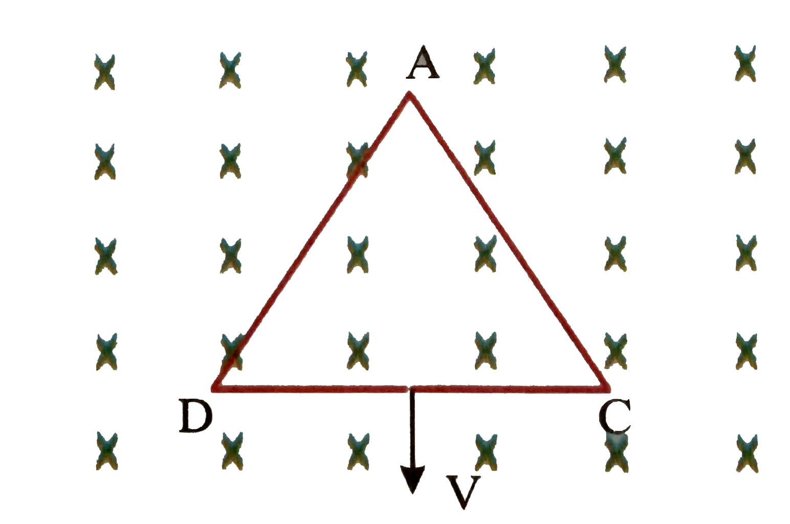
The induced current (i) versus time (t) graph will be as
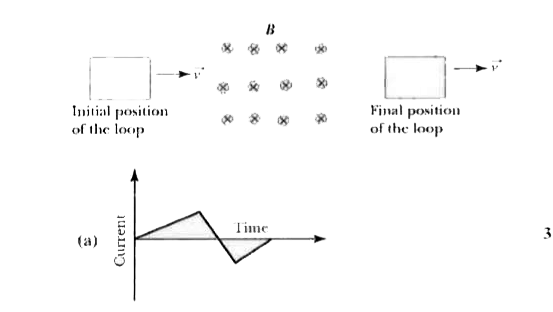
View SolutionA rectangular loop of wire in the plane of the paper starts outside a perpendicular uniform magnetic field directed into the paper as shown in the following figure. The loop is pulled with a constant velocity through the magnetic field and out the other side. Which of the following graphs would best represent the variation of the electric current in the wire with time?
View Solution
