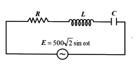
In the series L−C−R circuit shown in the figure, the rms voltage across the resistor and inductor are 400 V and 700 V respectively. If the applied voltage is E=500√2sin(ωt), then the peak voltage across the capacitor is

400 V.
400√2V.
800 V
800√2 V
The correct Answer is:B
(b) : rms potential differences are related as follows :
V2=V2R+(V2L−V2C)
⇒5002=4002+(7002−V2C)
⇒VC=400V
Hence peak voltage can be written as follows :
⇒V0C=400√2V
Hence option (b)is correct.
Topper's Solved these Questions
- ALTERNATING CURRENT BOOK - MODERN PUBLICATIONCHAPTER - ALTERNATING CURRENT EXERCISE - COMPETITION FILE (OBJECTIVE TYPE QUESTIONS) B. MULTIPLE CHOICE QUESTIONS
15 Videos
- ALTERNATING CURRENT BOOK - MODERN PUBLICATIONCHAPTER - ALTERNATING CURRENT EXERCISE - COMPETITION FILE JEE (MAIN) & OTHER STATE BOARDS FOR
26 Videos
- ALTERNATING CURRENT BOOK - MODERN PUBLICATIONCHAPTER - ALTERNATING CURRENT EXERCISE - Revision Exercises (Nuumerical problems )
18 Videos
- ATOMS BOOK - MODERN PUBLICATIONCHAPTER - ATOMS EXERCISE - Chapter Practice Test
16 Videos
Similar Questions
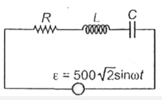
In a series RLC circuit the r.m.s. voltage across the resistor and the inductor are respectively 400 V and 700 V. If the equation for the applied Voltage is ε=500√2sinωt. then the peak voltage across the capacitor is

View SolutionIn a series LCR circuit, rms voltage across inductor and capacitor are found ot be 8 V and 5 V respectively. If applied voltage is 5 volts, then what is rms voltage across resistance in volts ?
View Solution
Knowledge Check
In an LCR series circuit the voltages across R,L and C at resonance are 40Vand60V respectively the applied voltage is .
A60VB40VC160VD√(40)2+(120)2VAn AC voltage is applied acrss a series combination of L and R. If the voltage drop across the resistor and inductor are 20V and 15V respectiely, then applied peak voltage is
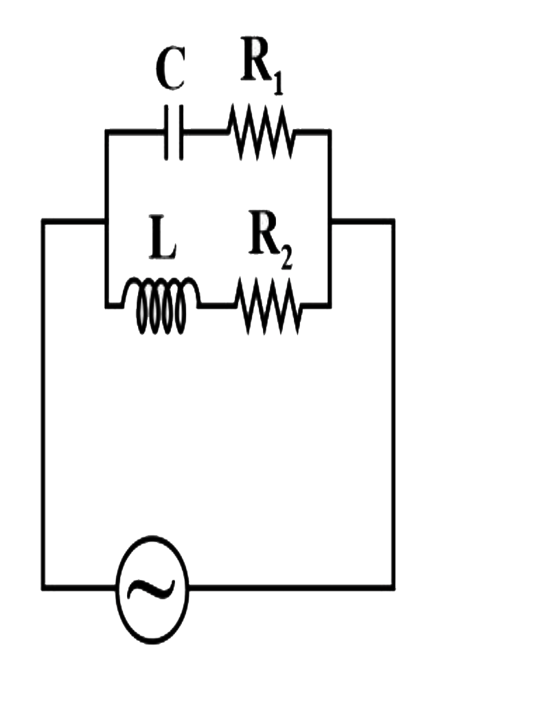
A25VB35VC25√2VD5√7VIn the given circuit the R.M.S values of voltages across the capacitor C, inductor L and resistor R1 are 12V, 10V and 5 V respectively. Then the peak voltage across R2 is
 A7√2VB√69VC√138VDnone of these
In a series CR circuit shown in figure,the applied voltage is 10V and the voltage across capacitor is found to be 8V
View SolutionIn a series LCR circuit the voltage across an inductor, capacitor and resistor are 20 V, 20 V and 40 V respectively. The phase difference between the applied voltage and the current in the circuit is
View Solution120 V AC voltage is applied to 10 ohm resistance. The peak voltage across the resistor is
View SolutionIn an LCR circuit, the voltages across the components are VL,VC and VR respectively. The voltage of source will be -
View SolutionIn a series resonant circuit, the AC voltage across resistance R, inductance L, and capacitance C are 5V,10V and 10V respectively. The AC voltage applied to the circuit will be
View Solution
