A half wave rectifer circuit is constracted using a p-n junction dode D load resistacne R and AC source as shown below
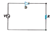
The current thourgh R varies as


for a half- wave rectifier ciruit diode D acts as closed circuit (with almost zero resistance ) for infinite resistance for the negative half cycle . So, no current flows during negative half cycle.
So the output is discontinous DC pulsating voltage as shown in figure (b) : Hence option (b) is correct.
Topper's Solved these Questions
- SEMICONDUCTOR ELECTRONICS METERIALS DEVICES AND SIMPLE CIRCUITS BOOK - MODERN PUBLICATIONCHAPTER - SEMICONDUCTOR ELECTRONICS METERIALS DEVICES AND SIMPLE CIRCUITS EXERCISE - COMPETION FILE (JEE(MAIN) & OTHER STATE BOARDS FOR ENGINEERING ENTRANCE )
31 Videos
- SEMICONDUCTOR ELECTRONICS METERIALS DEVICES AND SIMPLE CIRCUITS BOOK - MODERN PUBLICATIONCHAPTER - SEMICONDUCTOR ELECTRONICS METERIALS DEVICES AND SIMPLE CIRCUITS EXERCISE - COMPETION FILE( MULTIPLE CHOICE QUESTIONS )
17 Videos
- SEMICONDUCTOR ELECTRONICS METERIALS DEVICES AND SIMPLE CIRCUITS BOOK - MODERN PUBLICATIONCHAPTER - SEMICONDUCTOR ELECTRONICS METERIALS DEVICES AND SIMPLE CIRCUITS EXERCISE - REVISION EXERCISES (NUMERICAL PROBLEMS )
15 Videos
- RAY OPTICS AND OPTICAL INSTRUMENTSBOOK - MODERN PUBLICATIONCHAPTER - RAY OPTICS AND OPTICAL INSTRUMENTSEXERCISE - CHAPTER PRACTICE TEST
14 Videos
- WAVE OPTICALBOOK - MODERN PUBLICATIONCHAPTER - WAVE OPTICALEXERCISE - CHAPTER PRACTICE TEST
7 Videos
Similar Questions
Explain with the help of a circuit diagram, the working of a p−n junction diode as a half wave rectifier.
View SolutionIf in a p - n junction diode , a square input signal of 10 V is applied as shown
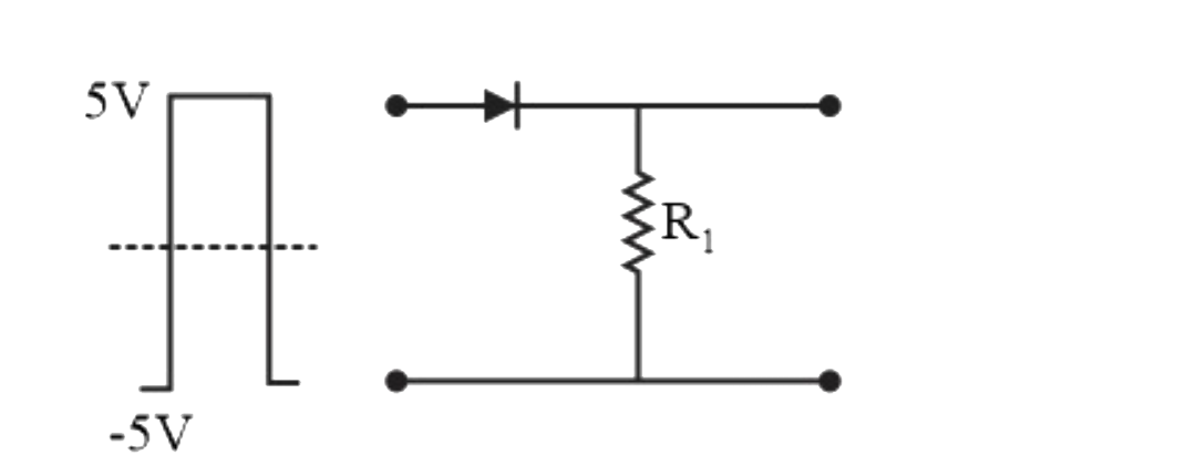
Then the output signal across RL will be
View SolutionIf in a p - n junction diode , a square input signal of 10 V is applied as shown
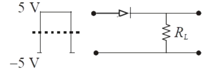
Then the output signal across RL will be
View SolutionExplain with the help of a circuit diagram, the working of a p-n junction diode as a half-wave rectifier.
View SolutionWith the help of circuit diagram explain, the working of p-n junction diode as half wave rectifier.
View SolutionExplain with a neat diagram, how a p-n junction diode is used as a half wave rectifier.
View SolutionWhat is the current through an ideal p-n junction diode shown in figure below ?
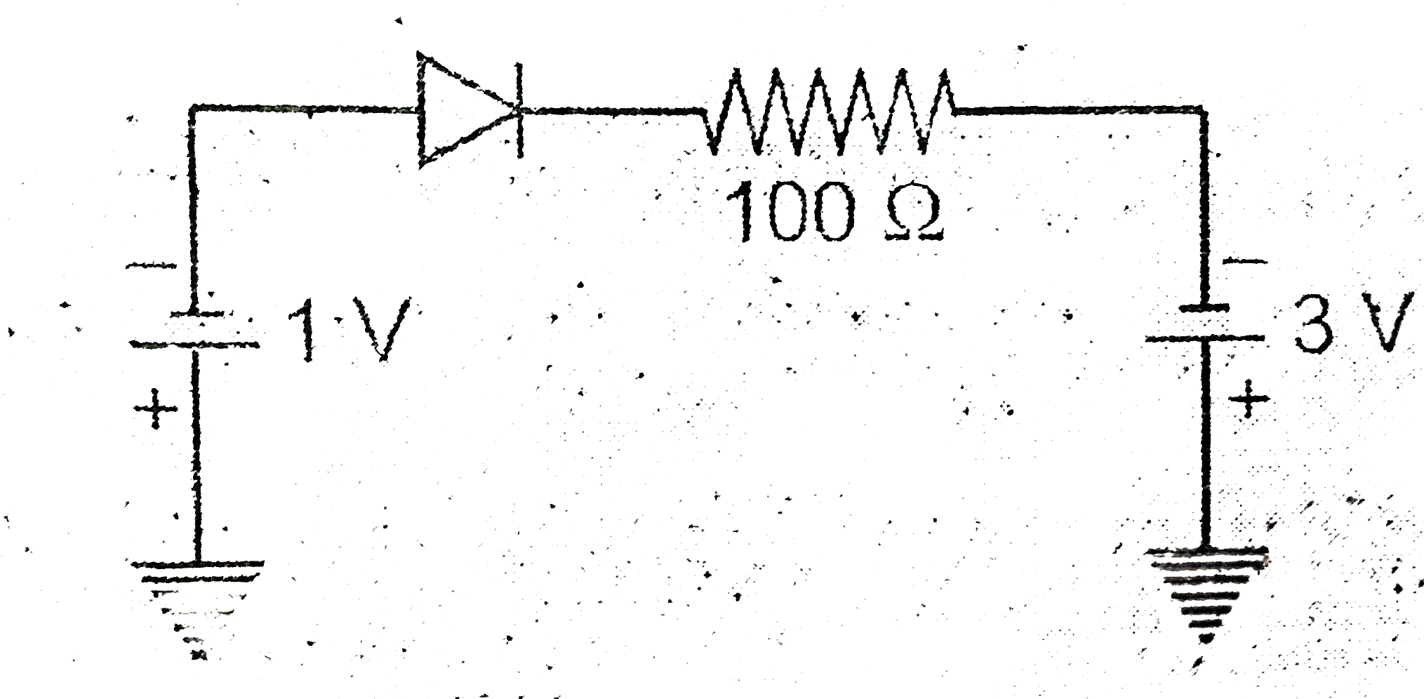
View SolutionFor half wave rectifier if load resistance Rd is 2kΩ and P-N junction resistance RL is 2kΩ determine rectification efficiency.
View SolutionAn ac source is connected to two circuits as shown Obtain current through resistance R at resonance in both the circuits
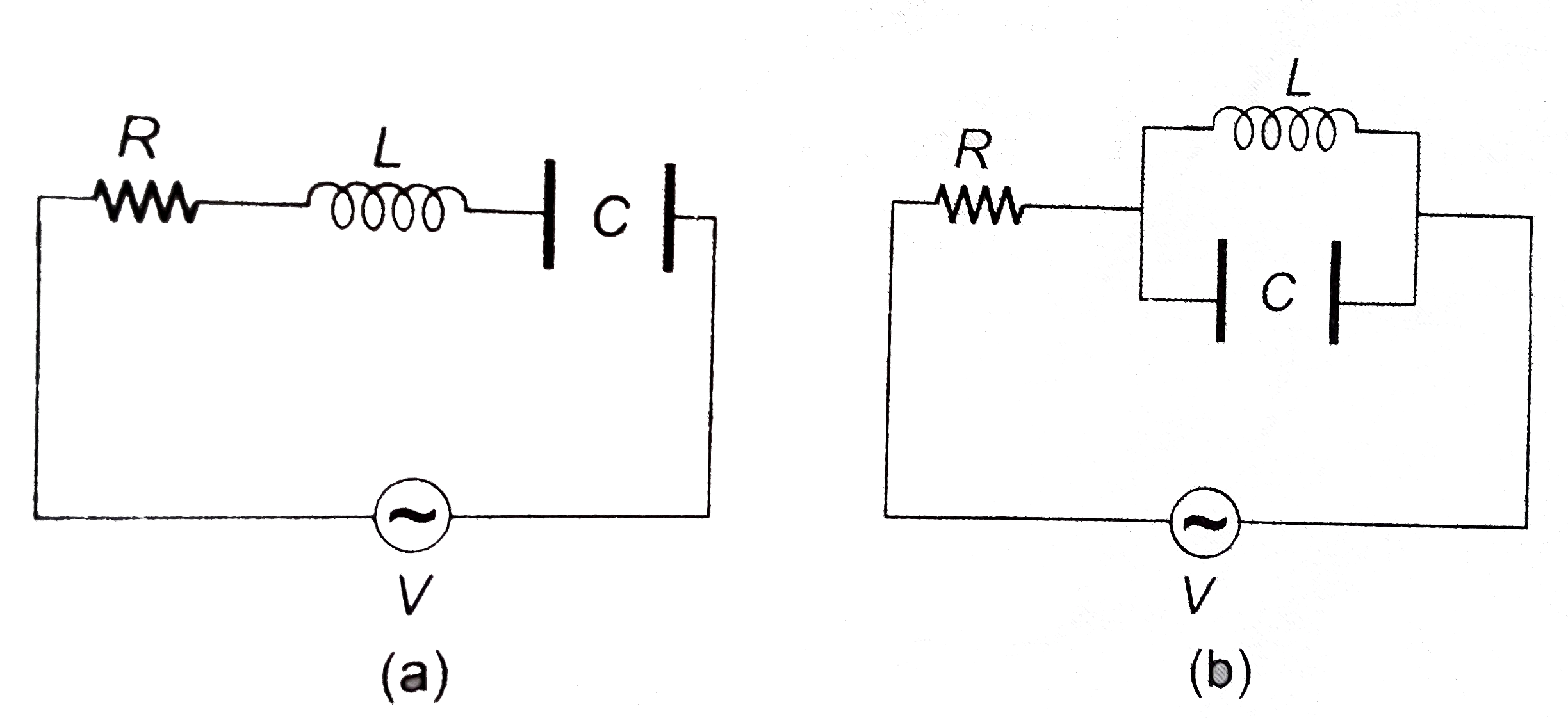 .
.
View SolutionA p−n diode is used in a half wave rectifier with a load resistance of 1000Ω. If the forward resistance (rf) of diode is 10Ω, calculate the efficiency of this half wave rectifier.
View Solution
